Science Education
>

An All-on-chip Method for Rapid Neutrophil Chemotaxis Analysis Directly from a Drop of Blood

PREPARAÇÃO DO INSTRUTOR
CONCEITOS
PROTOCOLO DO ALUNO
JoVE Journal
Imunologia e Infecção
É necessária uma assinatura da JoVE para visualizar este conteúdo.  Faça login ou comece sua avaliação gratuita.
JoVE Journal Imunologia e Infecção
An All-on-chip Method for Rapid Neutrophil Chemotaxis Analysis Directly from a Drop of Blood

All human sample collection protocols were approved by the Joint-Faculty Research Ethics Board at the University of Manitoba, Winnipeg.

1. Microfluidic Device Fabrication (Figure 1A)

  1. Design and print transparency mask.
    1. Design the device as detailed previously25. See Figure 1A.
      NOTE: The device includes two layers. The first layer (4 µm high) defines the cell docking barrier channel to trap the cells beside the gradient channel. The second layer (60 µm high) defines the gradient generating channel, the port and channel for cell loading, the chemical inlet reservoirs and waste outlet. The alignment marks are designed for the two layers. For the second layer, the length and width of the upstream serpentine input channel is 60 mm and 200 µm, respectively; the length and width of the downstream serpentine input channel is 6 mm and 280 µm, respectively.
    2. Print the first and second layer features to a transparency mask using a high-resolution printer.
      NOTE: The printing resolution depends on the minimum features in the design. In the current design, 32,000 dpi was chosen for 10 µm minimum feature.
  2. Clean the silicon wafer.
    1. Place a 3 in silicon wafer into the plasma cleaner. Apply vacuum for 3 min.
    2. Turn on the plasma power and set the level to HIGH. Use the oxygen plasma to treat the silicon wafer for 30 min.
    3. Turn off the plasma cleaner and take out the silicon wafer; the silicon wafer is ready for fabricating the device mold.
  3. Fabricate the first layer by photolithography in a cleanroom facility.
    NOTE: The exact fabrication parameters may vary depending on the fabrication facility.
    1. Dilute 10 mL SU-8 2025 with 10 mL SU-8 2000 in a glass breaker to prepare the designed photoresist. Leave the mixture in the fume hood for 10 min until the bubbles disappear.
    2. Carefully place the cleaned silicon wafer on the spinner with the suitable chuck and apply the vacuum to immobilize the silicon wafer.
    3. Carefully pour 3 mL of the photoresist mixture onto the center of the silicon wafer. Spin at 500 rpm for 5 s. Then spin at 3,000 rpm for 30 s to obtain a final 4 µm thickness photoresist coating on the silicon wafer.
    4. Carefully remove the silicon wafer from the spinner and bake the silicon wafer on a hotplate for 4 min at 95 °C.
    5. Carefully place the silicon wafer on a mask aligner and set the UV exposure time to 6 s. Carefully attach the transparency mask of the first layer on a transparent glass plate using adhesive tape.
    6. Gently place the transparent glass plate with the attached mask to the aligner and align the mask with the silicon wafer. Expose the silicon wafer to the UV to pattern the cell docking structure.
    7. Carefully remove the glass plate and take out the exposed silicon wafer. Bake the silicon wafer on a hotplate for 4 min at 95 °C.
    8. Transfer the silicon wafer to a fume hood and place it in a glass pan containing the SU-8 developer. Gently shake this for 30 s.
    9. Clean the silicon wafer using fresh SU-8 developer followed by isopropyl alcohol (IPA) inside the fume hood. Dry the silicon wafer by nitrogen gas inside the fume hood; the first layer is ready.
  4. Fabricate the second layer on the first layer.
    1. Use adhesive tape to cover the alignment marks on the first layer. Carefully place the silicon wafer with the first layer on the vacuum chuck of the spinner and apply vacuum to immobilize the silicon wafer.
    2. Pour 3 mL of SU-8 2025 photoresist on the silicon wafer. Spin the silicon wafer at 500 rpm for 5 s. Then spin at 2000 rpm for 30 s to obtain a final 60 µm thickness photoresist coating on the silicon wafer.
    3. Carefully remove the silicon wafer from the spinner and transfer it to a hotplate; bake at 65 °C for 2 min.
    4. Gently remove the adhesive tape to expose the alignment marks on the first layer. Place the silicon wafer on a hotplate and bake at 95 °C for 6 min.
    5. Carefully place the silicon wafer on a mask aligner and set the UV exposure time to be 18 s.
    6. Carefully attach the transparency mask of the second layer on a transparent glass plate using adhesive tape.
    7. Carefully place the glass plate with the attached mask to the aligner, and align the mask and the first layer on the silicon wafer by the crossing alignment marks using the inspection microscope of the aligner.
    8. Expose the photoresist coated silicon wafer to UV to pattern the cell loading and gradient channels.
    9. Carefully remove the glass plate and take out the silicon wafer. Bake the silicon wafer on a hotplate at 65 °C for 2 min and then transfer the silicon wafer to another 95 °C hot plate and bake for 6 min.
    10. Transfer the silicon wafer to the fume hood and place it in a glass pan containing the SU-8 developer. Gently shake this for 6 min.
    11. Clean the silicon wafer using fresh SU-8 developer followed by IPA inside the fume hood.
    12. Dry the silicon wafer using nitrogen gas inside the fume hood. Place the silicon wafer on a hotplate and hard bake the mold at 150 °C for 30 min; the second layer is ready.
  5. Master mold surface modification.
    NOTE: A silanization surface modification step is applied to the SU-8 mold to facilitate polydimethylsiloxane (PDMS) release from the mold in soft-lithography.
    1. Take 10 µL of tridecafluoro-1,1,2,2-tetrahydrooctyl (trichlorosilane) solution in a micropipette tip. Put the micropipette tip into a 15 mL plastic tube and loosen the cap of the tube.
    2. Place the tube and the SU-8 patterned silicon wafer inside a desiccator and apply the vacuum for 1 h; the mask mold is ready for fabricating the PDMS device.
  6. Fabricate the PDMS device.
    1. Prepare the PDMS solution by mixing 40 g PDMS base and 4 g curing agent in a plastic beaker. Place the prepared SU-8 master mold in a Petri dish and carefully pour 44 g PDMS solution onto the mold.
    2. Place the Petri dish in a desiccator and apply vacuum to degas the PDMS solution for 20 min. Then place the Petri dish in an oven and cure the PDMS at 80 °C for 2 h.
    3. After baking, take out the Petri dish and place it on a clean bench. Carefully cut and peel off the PDMS slab from the SU-8 mold.
    4. Punch out the cell loading port using a 3 mm diameter puncher. Punch out the chemical inlet reservoirs and the waste outlet using a 6 mm diameter puncher.
    5. Remove the dust on the surface of the PDMS slab using adhesive tape. Place the PDMS slab and a clean glass slide into the plasma machine. Apply the vacuum for 3 min.
    6. Turn on the plasma power and set the level to HIGH. Gently adjust the air valve and plasmatreat the PDMS slab and the glass slide for 3 min.
    7. Turn off the plasma power and release the vacuum. Carefully take out the PDMS slab and the glass slide using tweezers.
    8. Immediately place the PDMS slab (with channel structures face-down) on top of the glass slide; gently press the PDMS slab to bond it to the glass. Fill the microfluidic channel with deionized water immediately; the microfluidic device fabrication and assembly are completed.

2. Microfluidic Cell Migration Assay Preparation

  1. Microfluidic device preparation.
    1. Prepare 50 µg/mL fibronectin solution by diluting 50 µL of stock fibronectin solution (1 mg/mL) to 950 µL Dulbecco’s phosphate-buffered saline (DPBS) inside a biosafety cabinet.
    2. Prepare the migration medium by mixing 9 mL Roswell Park Memorial Institute medium (RPMI-1640) and 1 mL of RPMI-1640 with 4% bovine serum albumin (BSA).
    3. Remove the deionized water from the device.
    4. Add 100 µL fibronectin solution to the device from the outlet. Wait 3 min to ensure that all the channels are filled with fibronectin solution. Place the microfluidic device in a covered Petri dish for 1 h at room temperature.
    5. Remove the fibronectin solution from the device. Add 100 µL migration medium from the outlet. Wait 3 min to ensure that all the channels are filled with migration medium.
    6. Incubate the device for another 1 h at room temperature; the device is then ready for the chemotaxis experiment.
  2. Chemoattractant solution preparation for chemotaxis experiment.
    1. Prepare 100 nM fMLP solution in total 1 mL migration medium. Mix 5 µL of stock FITC-Dextran (10 kDa, 1 mM) with the fMLP solution in a 1.5 mL tube.
      NOTE: FITC-Dextran is used for gradient measurement. Alternatively, use Rhodamine as the gradient indicator. The fMLP chemoattractant solution is then ready for chemotaxis experiment.
  3. Sputum sample preparation.
    NOTE: Neutrophil chemotaxis induced by a gradient of sputum sample from COPD patients was tested as a clinical diagnostic application of this all-on-chip method.
    1. Obtain a human ethics protocol to collect sputum samples from COPD patients.
      NOTE: We obtained approvals to collect samples at the Seven Oaks General Hospital in Winnipeg (approved by the University of Manitoba).
    2. Obtain the informed written consent forms from all subjects.
    3. Collect COPD patients’ spontaneous sputum samples. Place 500 µL sputum sample in a 1.5 mL tube.
    4. Add 500 µL 0.1% dithiothreitol in the 1.5 mL tube and gently mix. Place the tube in a water bath at 37 °C for 15 min.
    5. Centrifuge the sample at 753 x g for 10 min and then collect the supernatant. Centrifuge the supernatant at 865 x g for 5 min and then collect the final supernatant. Store the collected supernatant inside a -80 °C freezer before use.
    6. When ready for chemotaxis experiment, thaw the sputum solution; transfer 900 µL migration medium to a 1.5 mL tube and mix with 100 µL sputum solution inside a biosafety cabinet; the sputum solution is then ready for chemotaxis experiment.
  4. Blood sample collection.
    1. Obtain a human ethics protocol to collect blood samples from healthy donors. Obtain the informed written consent forms from all blood donors.
      NOTE: Here samples were obtained at the Victoria General Hospital in Winnipeg (approved by the Joint-Faculty Research Ethics Board at the University of Manitoba).
    2. Collect the blood sample by venipuncture and put the sample into an EDTA-coated tube. Keep the tube in a biosafety cabinet before the experiment.

3. All-on-chip Chemotaxis Assay Operation

  1. On-chip cell isolation (Figure 1B).
    1. Place 10 µL whole blood in a 1.5 mL tube inside a biosafety cabinet.
      NOTE: Details of blood sample collection are in section 2.4.
    2. Add 2 µL antibody cocktail (Ab) and 2 µL magnetic particles (MP) from the neutrophil isolation kit (see the table of materials) into the 1.5 mL tube and gently mix; this will label cells in the blood except the neutrophils.
    3. Incubate the blood-Ab-MP mixture for 5 min at room temperature.
      NOTE: This will magnetically tag the antibody labeled cells in blood.
    4. Attach two small magnetic disks to the two sides of the cell loading port of the device. Aspirate the medium from all ports of the device.
    5. Slowly pipette 2 µL blood-Ab-MP mixture into the microfluidic device from the cell loading port.
      NOTE: The magnetically labeled cells are trapped to the side walls of the cell loading port while neutrophils will flow into the device and become trapped at the cell docking structure.
    6. Wait a few minutes until enough neutrophils are trapped at the cell docking area.
  2. Chemotaxis assay (Figure 1C).
    1. Place the microfluidic device on the temperature controlled microscope stage at 37 °C.
    2. Add 100 µL chemoattractant solution (fMLP or sputum solution) and 100 µL migration medium to their designated inlet reservoirs using two pipettors; this will generate a chemoattractant gradient in the gradient channel by continuous laminar flow-based chemical mixing assisted by a pressure balancing structure.
      NOTE: Details of the sputum collection from COPD patients are in section 2.3.
      1. For the medium control experiment, only add migration medium to both of the inlet reservoirs.
    3. Acquire the fluorescence image of FITC-Dextran in the gradient channel.
    4. Import the image to ImageJ software using the command “File|Open”.
    5. Measure the fluorescence intensity profile across the gradient channel using the command “Analyze|Plot Profile”.
    6. Export the measurement data to a spreadsheet for further plotting.
    7. Incubate the device on the temperature controlled microscope stage or in a conventional cell culture incubator for 15 min.
    8. Image the gradient channel using a 10X objective to record the cells’ final positions for data analysis.
    9. If needed, record the cell migration in the device by time-lapse microscopy.

4. Cell Migration Data Analysis (Figure 1C)

  1. Analyze the chemotaxis assay by calculating the cell migration distance from the docking structure as described below. See Figure 1C.
  2. Import the image into NIH ImageJ software (ver. 1.45).
  3. Select the center of each cell that moved into the gradient channel.
  4. Measure the coordinates of the selected cells for their final positions. Measure the coordinate of a point at the edge of the docking structure as the initial reference position.
  5. Export the measured coordinate data to a spreadsheet software (e.g. Excel). Calculate the migration distance of the cells as the difference between a cell’s final position and the initial reference position along the gradient direction.
  6. Calibrate the distance to a micrometer. Calculate the average and deviation of the migration distance of all cells as a measure of chemotaxis.
  7. Compare the migration distance in the presence of a chemoattractant gradient to the medium control experiment using the Student’s t-test.
  8. If the time-lapse images of the cell migration are recorded, the cell migration and chemotaxis can be further analyzed by cell tracking analysis15.
    NOTE: The materials required to construct and perform the all-on-chip chemotaxis assay are detailed in the table of materials.

An All-on-chip Method for Rapid Neutrophil Chemotaxis Analysis Directly from a Drop of Blood

Learning Objectives

Neutrophils are negatively selected from a drop of whole blood directly in the microfluidic device. The purity of the isolated neutrophils was verified by on-chip Giemsa staining and the results showed the typical ring-shaped and lobe-shaped nuclei of neutrophils (Figure 2A)25. This indicates an effective on-chip neutrophil isolation at high purity from a small volume of whole blood. Furthermore, the docking structure can effectively align cells next to the gradient channel before applying the chemical gradient (Figure 2B)25.

Gradient generation is based on the continuous laminar flow chemical mixing, and the flows are driven by the pressure difference from the different levels of the inlet and outlet solutions. No external pumps are required. The chemical gradient is established within a few minutes in the microfluidic device, which is characterized by the fluorescence intensity profile of FITC-Dextran across the gradient channel. The gradient is stable for at least 1 h, which is enough time for the current neutrophil chemotaxis experiment (Figure 1C).

To demonstrate the use of the all-on-chip method for cell migration research, the neutrophil chemotaxis in medium alone or in a fMLP gradient were compared. The test results showed that few cells crawled through the barrier channel in the medium control experiment. By contrast, many neutrophils rapidly moved through the barrier channel and migrated toward the 100 nM fMLP gradient (Figure 2B)25. The cell migration test is quantitatively measured by the migration distance, which is significantly higher for the fMLP gradient than the medium control (Figure 2C)25.

Furthermore, the all-on-chip method was demonstrated for potential clinical applications by comparing the neutrophil migration in medium alone to a gradient of sputum sample from COPD patients. The results showed a strong cell migration to the COPD sputum gradient, which is quantitatively indicated by the significantly higher migration distance compared to the medium control (Figure 2BC)25.

Figure 1
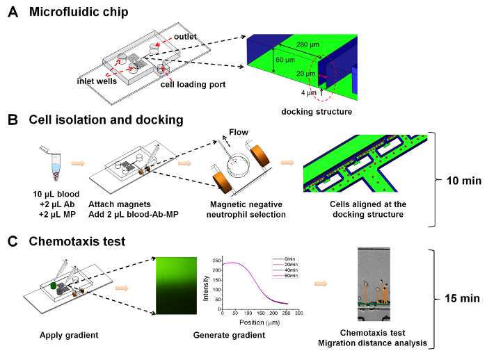
Figure 1: Illustration of the all-on-chip method for neutrophil chemotaxis analysis. (A) Illustration of the microfluidic device. The device includes two layers. The first layer (4 µm high) defines the cell docking barrier channel to trap the cells beside the gradient channel. The second layer (60 µm high) defines the gradient generating channel, the port and channel for cell loading, the chemical inlet reservoirs and the waste outlet. Alignment marks are designed for the two layers. For the second layer, the length and width of the upstream serpentine input channel is 60 mm and 200 µm, respectively; the length and width of the downstream serpentine input channel is 6 mm and 280 µm, respectively; (B) Illustration of the all-on-chip cell isolation method; (C) Illustration of the chemotaxis test. Please click here to view a larger version of this figure.

Figure 2
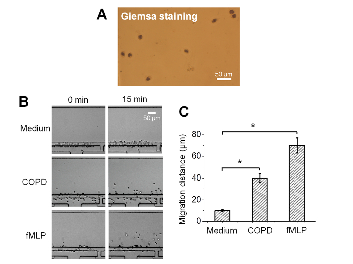
Figure 2: Representative results of the all-on-chip neutrophil chemotaxis analysis25. (A) Giemsa staining image (using a 60X objective) of the all-on-chip isolated cells in the microfluidic channel; (B) Comparison of the cell distribution in the medium control, a 100 nM fMLP gradient and a COPD sputum gradient; (C) The averaged cell migration distance in the gradient channel in the medium control, a fMLP gradient and a COPD sputum gradient. The error bars indicate the standard error of the mean (SEM). *indicates p <0.05 from the Student's t-test.The figures were adapted from reference25 with permission from World Scientific Publishing. Please click here to view a larger version of this figure.

List of Materials

Device fabrication
Mask aligner ABM N/A
Spinner Solitec 5000
Hotplate VWR 11301-022
Plasma cleaner Harrick Plasma PDC-001
Vacuum dessicator Fisher Scientific 08-594-15A
Digital scale Ohaus CS200
SU-8 2000 thinner Microchem SU-8 2000
SU-8 2025 photoresist Microchem SU-8 2025
SU-8 developer Microchem SU-8 developer
Si wafer Silicon, Inc LG2065
isopropyl alcohol Fisher Scientific A416-4
(tridecafluoro-1,1,2,2-tetrahydrooctyl) trichlorosilane Gelest 78560-45-9
Polydimethylsiloxane
(PDMS)
Ellsworth Adhesives 2065622
Petri Dish Fisher Scientific FB0875714
Glass slides Fisher Scientific 12-544-4
Cutting pad N/A N/A Custom-made
Punchers N/A N/A Custom-made
Name Source Catalog Number Comments
On-chip cell isolation and chemotaxis assay
RPMI 1640 Fisher Scientific SH3025502
DPBS Fisher Scientific SH3002802
Bovine serum albumin
(BSA)
Sigma-Aldrich SH3057402
Fibronectin VWR CACB356008
fMLP Sigma-Aldrich F3506-10MG
Magnetic disks Indigo Instruments 44202-1 5 mm in diameter,
1 mm thick
FITC-Dextran Sigma-Aldrich FD10S
Rhodamine
Sigma-Aldrich
R4127-5G
Giemsa stain solution Rowley Biochemical Inc. G-472-1-8OZ
EasySep Direct Human
Neutrophil Isolation
Kit
STEMCELL
Technologies Inc
19666
Dithiothreitol Sigma-Aldrich D0632
Nikon Ti-U inverted fluorescent microscope Nikon Ti-U
Microscope environmental chamber. InVivo Scientific N/A
CCD camera Nikon DS-Fi1

Preparação do Laboratório

Neutrophil migration and chemotaxis are critical for our body’s immune system. Microfluidic devices are increasingly used for investigating neutrophil migration and chemotaxis owing to their advantages in real-time visualization, precise control of chemical concentration gradient generation, and reduced reagent and sample consumption. Recently, a growing effort has been made by the microfluidic researchers toward developing integrated and easily operated microfluidic chemotaxis analysis systems, directly from whole blood. In this direction, the first all-on-chip method was developed for integrating the magnetic negative purification of neutrophils and the chemotaxis assay from small blood volume samples. This new method permits a rapid sample-to-result neutrophil chemotaxis test in 25 min. In this paper, we provide detailed construction, operation and data analysis method for this all-on-chip chemotaxis assay with a discussion on troubleshooting strategies, limitations and future directions. Representative results of the neutrophil chemotaxis assay testing a defined chemoattractant, N-Formyl-Met-Leu-Phe (fMLP), and sputum from a chronic obstructive pulmonary disease (COPD) patient, using this all-on-chip method are shown. This method is applicable to many cell migration-related investigations and clinical applications.

Neutrophil migration and chemotaxis are critical for our body’s immune system. Microfluidic devices are increasingly used for investigating neutrophil migration and chemotaxis owing to their advantages in real-time visualization, precise control of chemical concentration gradient generation, and reduced reagent and sample consumption. Recently, a growing effort has been made by the microfluidic researchers toward developing integrated and easily operated microfluidic chemotaxis analysis systems, directly from whole blood. In this direction, the first all-on-chip method was developed for integrating the magnetic negative purification of neutrophils and the chemotaxis assay from small blood volume samples. This new method permits a rapid sample-to-result neutrophil chemotaxis test in 25 min. In this paper, we provide detailed construction, operation and data analysis method for this all-on-chip chemotaxis assay with a discussion on troubleshooting strategies, limitations and future directions. Representative results of the neutrophil chemotaxis assay testing a defined chemoattractant, N-Formyl-Met-Leu-Phe (fMLP), and sputum from a chronic obstructive pulmonary disease (COPD) patient, using this all-on-chip method are shown. This method is applicable to many cell migration-related investigations and clinical applications.

Procedimento

Neutrophil migration and chemotaxis are critical for our body’s immune system. Microfluidic devices are increasingly used for investigating neutrophil migration and chemotaxis owing to their advantages in real-time visualization, precise control of chemical concentration gradient generation, and reduced reagent and sample consumption. Recently, a growing effort has been made by the microfluidic researchers toward developing integrated and easily operated microfluidic chemotaxis analysis systems, directly from whole blood. In this direction, the first all-on-chip method was developed for integrating the magnetic negative purification of neutrophils and the chemotaxis assay from small blood volume samples. This new method permits a rapid sample-to-result neutrophil chemotaxis test in 25 min. In this paper, we provide detailed construction, operation and data analysis method for this all-on-chip chemotaxis assay with a discussion on troubleshooting strategies, limitations and future directions. Representative results of the neutrophil chemotaxis assay testing a defined chemoattractant, N-Formyl-Met-Leu-Phe (fMLP), and sputum from a chronic obstructive pulmonary disease (COPD) patient, using this all-on-chip method are shown. This method is applicable to many cell migration-related investigations and clinical applications.

Tags