Science Education
>

Methods for In Vivo Biomechanical Testing on Brachial Plexus in Neonatal Piglets

PREPARAÇÃO DO INSTRUTOR
CONCEITOS
PROTOCOLO DO ALUNO
JoVE Journal
Bioengenharia
É necessária uma assinatura da JoVE para visualizar este conteúdo.  Faça login ou comece sua avaliação gratuita.
JoVE Journal Bioengenharia
Methods for In Vivo Biomechanical Testing on Brachial Plexus in Neonatal Piglets

Institutional Animal Care and Use Committee at Drexel University approved all procedures (#20704).

1. Animal Arrival and Acclimation

  1. Quarantine 1–2 day-old piglets for at least 24 h after arrival.
  2. House piglets in clean and sanitized stainless-steel cages (36 in x 48 in x 36 in) on aspen chip bedding and feed ad libitum with pig milk replacer.
  3. Maintain the room temperature at 85 °F to ensure a thermo-neutral environment.

2. Day of Experiment

  1. Remove the feed 2 h prior to the experiment.
  2. Inject piglets with an intramuscular injection of ketamine (10–40 mg/kg)/xylazine (1.5–3.0 mg/kg IM) and transport via a transport cage to the surgical space.

3. Induction and Maintenance of Anesthesia

  1. Administer 4% isoflurane inhalation anesthetic mixed in oxygen by nose cone and confirm that the animal is deeply anesthetized by assessing the absence of palpebral and withdrawal reflexes.
  2. Intubate the animal by placing it in the supine position and use a laryngoscope (straight blade) to help guide the intubation tube (diameter 2.5–2 mm) into the trachea.
  3. Place the animal on the ventilator once intubation tube is secured.
  4. Ensure that piglets receive a mix of isoflurane (0.25%–3% maintenance), oxygen, and nitrous oxide.
  5. Provide a dose of fentanyl (10 μg/kg) and continue giving a dose every 1–2 h to ensure continued adequate depth of analgesia and sedation and to avoid motion artifacts that could risk dislodgment of the endotracheal tube.
  6. Establish intravenous (IV) access in the subcutaneous abdominal vein or any other peripheral vein.
  7. Establish the arterial line through the femoral artery. This can be done non-invasively or by performing a cut-down.

4. Monitoring and Care

  1. Monitor the depth of anesthesia by confirming the absence of canthal reflex and absence of withdrawal response to toe pinch.
  2. Perform continuous monitoring of physiological parameters during anesthesia and throughout the experiment, which includes arterial blood pressure, electrocardiography (ECG), end-tidal CO2, pulse oximetry, and body temperature.
  3. Monitor blood gases and blood sugars every 0.5–1 h and give intravenous fluids (50% dextrose and 50% normal saline) to animals anesthetized longer than 1 h at ~100 cc/kg/day, as needed, to ensure euglycemia.
  4. Monitor the animal's anesthetic plane closely and frequently. Provide analgesia and/or increase inhalant anesthesia.
  5. Maintain the animal at normal oxygen tension by controlling the ventilator parameters and drug dosages as needed to ensure normoxia, then place the animal on a temperature-regulated circulating water blanket such that normal body temperature is maintained at 39 °C for the duration of the experiment.

5. Brachial Plexus Surgery

  1. Place the animal in a supine position on the operating table after proper anesthesia as described in section 3, with the upper limb in abduction, exposing the axillary region.
  2. Use any surgical drape to cover the animal. Use clean but non-sterile techniques.
  3. Expose the brachial plexus complex on both sides of the spine by making a midline incision (using a #10 blade) over the skin and fascia overlying the trachea, down to the upper third of the sternum, corresponding to spine levels between C3–T3.
  4. Extrapolate the incision using the forceps and hemostat horizontally on each side from the suprasternal notch along the edge of the clavicle to the upper arm, while sparing the cephalic and basilic veins.
  5. Release the superior and inferior flaps by blunt dissection using scissors and forceps, allowing access to the cervical and thoracic regions of the brachial plexus, respectively.
  6. Identify the axis (C2) and first rib at the T1. Using these landmarks, identify the lower three cervical (C6–C8) and first thoracic (T1) spinal vertebral foramen, then examine the plexus carefully to locate bifurcations of the divisions (M shape) to achieve exposure.
  7. Label (using nerve loops) the brachial plexus regions above these bifurcations closer to the spine as root/trunk and label those below these bifurcations as chord followed by the nerve, which are located closer to the arm.

6. Biomechanical Testing

  1. Set-up of the biomechanical testing device
    NOTE: A custom-built mechanical testing device was designed and fabricated to perform in vivo stretch of the BP (Figure 1).
    1. Attach the base of the set-up to a cart.
    2. Attach the electromechanical actuator onto the base using large C-clamps. The actuator is capable of providing 150 lb of force, 10" stroke, and speed of 15 mm/s. The speed can be reduced to 0.2 mm/s and still function as desired.
    3. Attach the 200 N load cell to actuator.
    4. Attach (screw-in) a clamp to the load cell that consists of padded plexiglass, which prevents the stress concentration at the clamping site.
    5. Attach a camera to a tripod. Ensure that the camera has the capability of recording up to 120 f/s at a resolution of 658 x 4926 pixels.
    6. Attach USB cables from the camera, actuator, and load cell to the computer to integrate and synchronize all components of the set-up.
    7. Plug the computer, actuator, and load cell into a power source.
  2. Calibrate the load cell prior to recording the applied loads. To do so, perform the steps below:
    1. Set the actuator at a 90° angle using the adjustable handle and checking the angle with a protractor.
    2. Open the software that works with the load cell (Table of Materials). Press the Start button to show a live readout of voltage.
    3. Hang weights from the clamp ranging from 0–1,000 g in increments of 100 g from the setup and record the measured voltages.
    4. Calculate the linear equation of the voltages and weights by finding the slope (m) and intercept (b). This is done using a spreadsheet program and the included slope function to calculate b from the Equation 1 below. Insert Equation 2 shown below into the mechanical set-up code.
      Equation 1: b = y – mx
      Where: y is the weight, x is the voltage, m is the slope, and b is the intercept (constant).
      Equation 2: y = mx + b
      Where: y is the weight, x is the voltage, m is the slope, and b is the constant.
  3. Testing: the BP nerve is cut and anchored to the testing set-up by custom-built clamp.
    1. Cut the BP nerve using fine scissors.
    2. Clamp the cut side of the BP nerve in the custom-built clamp as shown in Figure 1.
    3. Manually place black acrylic paint or India ink on the clamped BP segment (Figure 2).
    4. Place a calibration grid, which is a 1 cm ruler, flat within the animal to set the scale for data analysis.
    5. Use the camera's software to view the camera's placement directly over the tested segments, thereby allowing the monitoring of the motion/displacement of the markers and determining the actual tissue strain at any timepoint.
    6. Record initial measurements such as the height at which the nerve inserts into the body from the table and the height of the clamp from the table, the angle of the actuator, and the full length of the tissue.
    7. Open the programming software (table containing the graphical user interface [GUI] as shown in Figure 3).
    8. Run the GUI by pressing the Run button.
    9. Initialize the system by pressing the Initialize button.
    10. Tare the system by pressing the Tare button.
    11. Stretch the BP segment by pressing the start test button. This pulls the tissue at an assigned rate of 500 mm/min until complete failure occurs in any segment of the BP. This stretch rate is selected based on the available literature4,8,18. The program also saves a video file, the applied tensile load, displacement of the tissue, and duration of the test.
    12. Record the failure site, which is the point at which the tissue ruptures.
  4. Euthanasia: euthanize piglets at the end of the experiment with a lethal dose of pentobarbital (120 mg/kg i.v.).
  5. Data analysis: use motion tracking software for the analysis of the videos acquired during testing.
    1. Open the video file from the experiment within the motion tracking software by selecting File | Open Video File.
    2. Use the calibration grid to setup the scale in the motion tracking software using the Line tool, right-clicking on the line after it is drawn, selecting Calibrate Measure, and entering a known value in centimeters (Figure 4).
    3. Track the markers on the tissue within the motion tracking software by right-clicking on the video and selecting Track Path and aligning the center of the marker with the marker on the tissue and tacking it until rupture.
    4. Export the x- and y-coordinates from the markers by selecting File Export to Spreadsheet so that it can be used to calculate the strains.
    5. Import the data into a programming software to calculate the distance between the x- and y-coordinates over time to calculate the strains.
    6. Calculate strain values at each timepoint by dividing the change in distance by the original distance after accounting for changes in inclination during stretch. The actual strain values are determined between each pair of adjacent markers at each timepoint. The average of these strains is also calculated.

Methods for In Vivo Biomechanical Testing on Brachial Plexus in Neonatal Piglets

Learning Objectives

A representative load-time plot and strains from four segments of BP plexus (between four markers) are shown in Figure 5 and Figure 6, respectively. The obtained failure load of 8.3 N at 35% average failure strain reports the biomechanical responses of neonatal BP when subjected to stretch. Some regions of the nerve undergo higher strains than others, indicative of non-uniform injury along the length of the nerve. The camera data allows reporting the location of failure being proximal to the foramen.

Figure 1
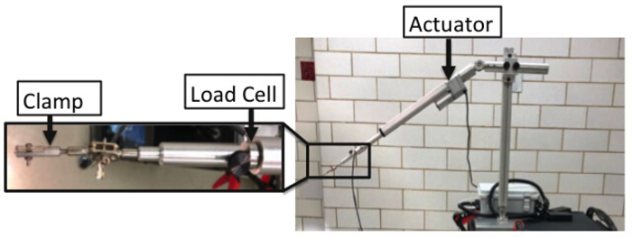
Figure 1: Details of in vivo mechanical testing device including the actuator, load cell, and clamp. Please click here to view a larger version of this figure.

Figure 2
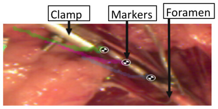
Figure 2: Markers placed over the BP segments to record strains sustained by the tissue during stretch. Please click here to view a larger version of this figure.

Figure 3
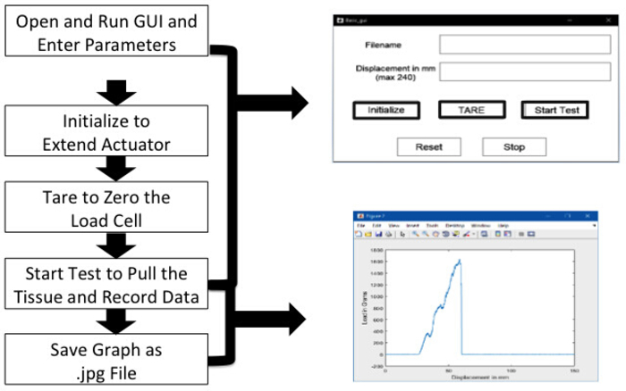
Figure 3: Steps for data acquisition using graphical user interface. Please click here to view a larger version of this figure.

Figure 4
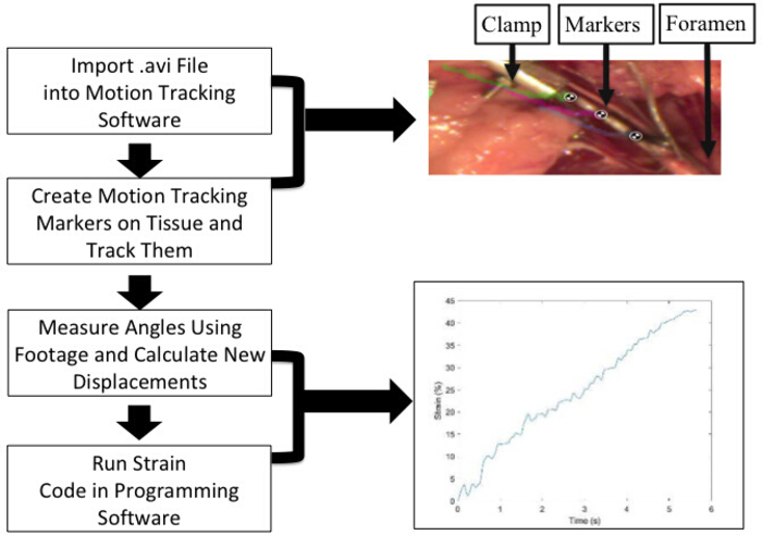
Figure 4: Marker tracking and strain analysis details. Test videos saved in AVI format are imported in the tracking software. Strain between each marker and the first and last markers are obtained as detailed. An average of between markers strains is used to report the failure strains. An example of nerve stretch with three markers and the calculated average strain-time plot are shown here, with reported failure strains of 43%. Please click here to view a larger version of this figure.

Figure 5
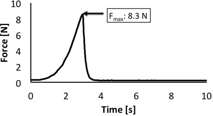
Figure 5: Maximum load reported during failure. Load cell attached to the actuator acquires the load data during stretch. The data are used to obtain a load-time plot as shown. Please click here to view a larger version of this figure.

Figure 6
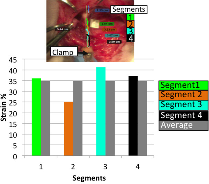
Figure 6: Strains reported in four different segments of the stretched plexus. Strains are calculated between each marker and compared against average strains obtained from all four segments (between each of the two adjacent markers). Some regions of the nerve undergo higher strains than others and the average strains indicative of non-uniform injury along the length of the nerve. Please click here to view a larger version of this figure.

List of Materials

Omega Subminature Tension & Compression Load Cell Omega LCM201-200N 200N load cell
Basler acA640-120uc camera Basler acA640-120uc
Feedback Linear Actuator Progressive Automations PA-14P 10" stroke, 150lb force, 15mm/s speed
Motion Tracking Software Kinovea N/A Open Source
Proramming Software – MATLAB Mathworks N/A version 2018A
Surgical instruments
Forceps Fine Science Tools Inc 11006-12 and 11027-12 or 11506-12
Hemostats Fine Science Tools Inc 13009-12
Scissors Fine Science Tools Inc 14094-11 or 14060-09

Preparação do Laboratório

Neonatal brachial plexus palsy (NBPP) is a stretch injury that occurs during the birthing process in nerve complexes located in the neck and shoulder regions, collectively referred to as the brachial plexus (BP). Despite recent advances in obstetrical care, the problem of NBPP continues to be a global health burden with an incidence of 1.5 cases per 1,000 live births. More severe types of this injury can cause permanent paralysis of the arm from the shoulder down. Prevention and treatment of NBPP warrants an understanding of the biomechanical and physiological responses of newborn BP nerves when subjected to stretch. Current knowledge of the newborn BP is extrapolated from adult animal or cadaveric BP tissue instead of in vivo neonatal BP tissue. This study describes an in vivo mechanical testing device and procedure to conduct in vivo biomechanical testing in neonatal piglets. The device consists of a clamp, actuator, load cell, and camera system that apply and monitor in vivo strains and loads until failure. The camera system also allows monitoring of the failure location during rupture. Overall, the presented method allows for a detailed biomechanical characterization of neonatal BP when subjected to stretch.

Neonatal brachial plexus palsy (NBPP) is a stretch injury that occurs during the birthing process in nerve complexes located in the neck and shoulder regions, collectively referred to as the brachial plexus (BP). Despite recent advances in obstetrical care, the problem of NBPP continues to be a global health burden with an incidence of 1.5 cases per 1,000 live births. More severe types of this injury can cause permanent paralysis of the arm from the shoulder down. Prevention and treatment of NBPP warrants an understanding of the biomechanical and physiological responses of newborn BP nerves when subjected to stretch. Current knowledge of the newborn BP is extrapolated from adult animal or cadaveric BP tissue instead of in vivo neonatal BP tissue. This study describes an in vivo mechanical testing device and procedure to conduct in vivo biomechanical testing in neonatal piglets. The device consists of a clamp, actuator, load cell, and camera system that apply and monitor in vivo strains and loads until failure. The camera system also allows monitoring of the failure location during rupture. Overall, the presented method allows for a detailed biomechanical characterization of neonatal BP when subjected to stretch.

Procedimento

Neonatal brachial plexus palsy (NBPP) is a stretch injury that occurs during the birthing process in nerve complexes located in the neck and shoulder regions, collectively referred to as the brachial plexus (BP). Despite recent advances in obstetrical care, the problem of NBPP continues to be a global health burden with an incidence of 1.5 cases per 1,000 live births. More severe types of this injury can cause permanent paralysis of the arm from the shoulder down. Prevention and treatment of NBPP warrants an understanding of the biomechanical and physiological responses of newborn BP nerves when subjected to stretch. Current knowledge of the newborn BP is extrapolated from adult animal or cadaveric BP tissue instead of in vivo neonatal BP tissue. This study describes an in vivo mechanical testing device and procedure to conduct in vivo biomechanical testing in neonatal piglets. The device consists of a clamp, actuator, load cell, and camera system that apply and monitor in vivo strains and loads until failure. The camera system also allows monitoring of the failure location during rupture. Overall, the presented method allows for a detailed biomechanical characterization of neonatal BP when subjected to stretch.

Tags