A simple microfluidic device has been developed to perform anesthetic free in vivo imaging of C. elegans, intact Drosophila larvae and zebrafish larvae. The device utilizes a deformable PDMS membrane to immobilize these model organisms in order to perform time lapse imaging of numerous processes such as heart beat, cell division and sub-cellular neuronal transport. We demonstrate the use of this device and show examples of different types of data collected from different model systems.
Method Article
Simple Microfluidic Devices for in vivo Imaging of C. elegans, Drosophila and Zebrafish
In This Article
Summary
Abstract
Micro fabricated fluidic devices provide an accessible micro-environment for in vivo studies on small organisms. Simple fabrication processes are available for microfluidic devices using soft lithography techniques 1-3. Microfluidic devices have been used for sub-cellular imaging 4,5, in vivo laser microsurgery 2,6 and cellular imaging 4,7. In vivo imaging requires immobilization of organisms. This has been achieved using suction 5,8, tapered channels 6,7,9, deformable membranes 2-4,10, suction with additional cooling 5, anesthetic gas 11, temperature sensitive gels 12, cyanoacrylate glue 13 and anesthetics such as levamisole 14,15. Commonly used anesthetics influence synaptic transmission 16,17 and are known to have detrimental effects on sub-cellular neuronal transport 4. In this study we demonstrate a membrane based poly-dimethyl-siloxane (PDMS) device that allows anesthetic free immobilization of intact genetic model organisms such as Caenorhabditis elegans (C. elegans), Drosophila larvae and zebrafish larvae. These model organisms are suitable for in vivo studies in microfluidic devices because of their small diameters and optically transparent or translucent bodies. Body diameters range from ~10 μm to ~800 μm for early larval stages of C. elegans and zebrafish larvae and require microfluidic devices of different sizes to achieve complete immobilization for high resolution time-lapse imaging. These organisms are immobilized using pressure applied by compressed nitrogen gas through a liquid column and imaged using an inverted microscope. Animals released from the trap return to normal locomotion within 10 min.
We demonstrate four applications of time-lapse imaging in C. elegans namely, imaging mitochondrial transport in neurons, pre-synaptic vesicle transport in a transport-defective mutant, glutamate receptor transport and Q neuroblast cell division. Data obtained from such movies show that microfluidic immobilization is a useful and accurate means of acquiring in vivo data of cellular and sub-cellular events when compared to anesthetized animals (Figure 1J and 3C-F 4).
Device dimensions were altered to allow time-lapse imaging of different stages of C. elegans, first instar Drosophila larvae and zebrafish larvae. Transport of vesicles marked with synaptotagmin tagged with GFP (syt.eGFP) in sensory neurons shows directed motion of synaptic vesicle markers expressed in cholinergic sensory neurons in intact first instar Drosophila larvae. A similar device has been used to carry out time-lapse imaging of heartbeat in ~30 hr post fertilization (hpf) zebrafish larvae. These data show that the simple devices we have developed can be applied to a variety of model systems to study several cell biological and developmental phenomena in vivo.
Protocol
1. SU8 Master Fabrication
- Design the microfluidic structures using Clewin software and print it using 65,024 DPI laser plotter with minimum feature size of 8 μm on circuit board film.
- Clean 2 cm X 2 cm silicon wafers with native oxide in 20% KOH for 1 min and rinse in deionized water; one wafer each for the flow layer and its corresponding control layer.
- Blow dry the pieces with nitrogen gas and dehydrate on a hot plate at 120 °C for 4 hr. Allow the pieces to cool down to room temperature before proceeding to the next step.
- Place silicon pieces one at a time on the spinner chuck and turn on the vacuum. Cover the silicon surfaces with ~20 μl hexamethyl-disilazane (HMDS) and coat them using a SPIN150 spinner at 500 rpm for 5 sec followed by 3,000 rpm for 30 sec.
- Cover silicon wafers completely with ~1.5 ml of SU8-2025 (http://www.microchem.com/Prod-SU82000.htm) and coat wafers using SPIN150 spinner at 500 rpm for 5 sec followed by 2,000 rpm for 30 sec. This spinning protocol produces a photoresist thickness of ~40 μm that is suitable for the control and flow layers for early larval stages of C. elegans.
- Spin ~1.5 ml SU8-2050 using SPIN150 spinner at 500 rpm for 5 sec followed by 2,000 rpm for 30 sec to obtain a photoresist thickness of ~80 μm that is suitable for flow layer fabrication for late larval stages of C. elegans, basal flow layer for Drosophila/zebrafish larvae and their corresponding control layers.
- Place the silicon pieces on hot plate with the SU8 coated layer on top. Soft bake the coated silicon pieces at 65 °C for 1 min followed by 95 °C for 10 min. Allow the pieces to cool down to room temperature before proceeding to the next step.
- Place the soft-baked silicon pieces on the exposure stage with SU8-2025 coated surface on the top facing the UV lamp. Use the photo mask with design I (L1, Figure 1B) and design II (L2, Figure 1B) for the flow layer and control layer pattern respectively for early larval stages of C. elegans. Place the photo mask on top of the SU8 layer and ensure the mask is flat against the coated layer. Open the shutter of the UV lamp and expose the soft-baked SU8 wafers to 200 Watt UV lamp through the photo mask for 15 sec.
- Use the photo mask with design I (L1, Figure 1B) and design II (L2, Figure 1B) on SU8-2050 coated pieces (prepared in step 1.6) to fabricate the flow layer and control layer for late larval stages of C. elegans. Use the photo mask with the design I (L1, Figure 1C) and design II (L2, Figure 1C) for the basal flow layer and control layer respectively for Drosophila/zebrafish larvae on wafers coated with SU8-2050 (prepared in step 1.6). Expose the SU8 surfaces through the photo mask to the 200 Watt UV lamp for 15 sec.
- Place the exposed silicon pieces on a hot plate with the coated layer on top. Post bake the wafers at 65 °C for 1 min followed by 95 °C for 10 min. Allow the pieces to cool down before proceeding to the next step.
- Develop the pieces using the SU8 developer solution for 20 min. Rinse the pieces in Iso-Propyl Alcohol (IPA) and blow dry using nitrogen gas.
- Place the silicon pieces in a desiccator with the SU8 pattern on top. Coat the pieces with 50 μl of tricholoro (1H,1H,2H,2H-perfluorooctyl) silane vapor in a desiccator for 2 hr.
Precautions: Take safety precautions for chemical handling during KOH treatment, photoresist coating and developing. Silane vapor coating should be performed inside a desiccator in a ventilated area. Protect SU8 resist from over exposure to light. Use protective eyewear with an UV light source.
2. PDMS Mold Fabrication
- Prepare 10:1 PDMS by combining 50 g of Sylgard 184 base with 5 g of curing agent in a plastic cup. Mix the content manually for ~3 min. Degas the mixture inside a desiccator to remove all air bubbles formed during mixing.
- Pour a 5 mm thick PDMS mixture over the silicon wafers with SU8 pattern of design II, for control layer, gently to avoid formation of air bubbles. In case bubbles are formed during pouring, degas the PDMS on the SU8 pattern in low vacuum to remove all the bubbles.
- Place the silicon wafers with SU8-2025 pattern of design I, for the flow layer, on spinner chuck and turn on the vacuum to hold them. Cover the wafers with ~1 ml of PDMS mix and coat the wafers using SPIN150 spinner at 500 rpm for 5 sec followed by 1,500 rpm for 30 sec.
- Coat ~1 ml PDMS mix on silicon wafers with the 80 μm SU8-2050 pattern of design I (L1, Figure 1B), for the flow layer for late larval stages of C. elegans using the SPIN150 spinner at 500 rpm for 5 sec followed by 1,000 rpm for 30 sec. Coat a thick layer of PDMS mix on the silicon pieces with SU8-2050 pattern of flow layer design I (L1, Figure 1C) for Drosophila/zebrafish larvae, using SPIN150 spinner at 500 rpm for 35 sec.
- Bake PDMS coated silicon pieces of design I and wafers with corresponding design II for control layer containing PDMS for C. elegans and/or Drosophila/zebrafish larvae in a hot air convection oven at 50 °C for 6 hr.
- Cut out the PDMS piece from the silicon substrate containing the SU8 pattern II for C. elegans and/or Drosophila/zebrafish larvae using a sharp blade. Punch a small hole of ~1 mm diameter on top of the reservoir connecting the main trap in the PDMS mold using a Harris puncher.
- Place the punched PDMS block (containing the 40 μm thick mold for control layer L2) on a plastic tray, with the molded side of the control layer facing up. Place the PDMS coated silicon wafer containing the 40 μm thick SU8 design I on the same tray, with the PDMS coated surface facing up. Insert the tray inside the chamber of plasma cleaner and turn on the vacuum for 2 min. Subsequently, turn on the plasma power and lower the chamber pressure until the chamber turns light pink in color. Expose both surfaces to 18 Watt air plasma under low vacuum for 2 min.
- Place the punched PDMS block removed from the 80 μm thick SU8 master containing pattern II for late larval stages of C. elegans or Drosophila/zebrafish larvae on a plastic tray, with the molded side of the control layer facing up. Place the corresponding baked PDMS layer spin coated on the silicon wafer containing 80 μm thick design I for later C. elegans stages or Drosophila/zebrafish larvae simultaneously on the same tray with the flat PDMS coated surface facing up. Use the same protocol mentioned above to expose them to air plasma.
- Place the two plasma treated surfaces for C. elegans and/or Drosophila/zebrafish larvae together with gentle pressure and bake them in hot air convection oven at 50 °C for 2 hr.
- Cut out the bonded devices from the silicon substrate with SU8 design I for C. elegans and/or Drosophila/zebrafish larvae. Punch access holes at the inlet and outlet reservoirs of the flow channel.
- Place the bonded PDMS mold on a plastic tray for C. elegans, with the molded side of the flow layer design facing up. Clean glass cover slip (22 X 22 mm, No. 1 thickness) and place it on the same plastic tray. Insert the tray containing PDMS mold and glass cover slip inside the plasma chamber. Expose the bottom PDMS surface of the device and glass cover slip to 18 Watt air plasma at low pressure for 2 min. Place the two plasma treated surfaces with gentle pressure and bake them in hot air convection oven at 50 °C for 2 hr.
- Store the device in a clean environment for future use.
3. Additional Steps for Drosophila/Zebrafish Device
- Expose clean glass surface of size 2 cm X 2 cm with 50 μl of tricholoro(1H,1H,2H,2H-perfluorooctyl) silane vapor in a desiccator for 2 hr.
- Spin ~1 ml of 10:1 PDMS mix prepared in step 2.1 on the silanized glass surface using SPIN150 spinner at 500 rpm for 35 sec. Bake the PDMS coated glass substrates in a hot air oven at 50 °C for 6 hr with the coated surface facing up. Allow the PDMS layer to cool down to room temperature before proceeding to the next step.
- Punch the coated layer using a custom built sharp metal puncher at the middle of the PDMS, to form the PDMS spacer layer. The shape of the metal puncher is designed similar to the flow design for Drosophila/zebrafish (L1, Figure 1C).
- Expose the PDMS spacer layer and the single-bonded block (flow layer and control layer, made in step 2.9 for Drosophila/zebrafish larvae) to 18 Watt air plasma using plasma cleaner at low vacuum. Place the two plasma treated surfaces together and bake them in a hot air oven at 50 °C for 2 hr.
- Cut the bonded device from the glass, punch access holes at the inlet and outlet reservoirs and bond it to a glass cover slip (22 X 22 mm, No. 1 thickness) using a plasma cleaner as mentioned in step 2.11. This would produce an immobilization device for first instar Drosophila larvae with a channel height of ~500 μm. For zebrafish larvae, duplicate the PDMS spacer layer fabrication process with an additional bonding step. The dual layer of PDMS-S produces a channel height of 900 μm for 30 hfp zebrafish larvae.
Precautions: Avoid dust particles during device fabrication. Two plasma cleaned surfaces need to be completely dust free for proper bonding. Store the devices in a desiccator in situations where a special clean room is not available in order to minimize accumulation of dust particles in devices.
4. Using PDMS Membrane
- Connect one end of a micro-flex tube (inner diameter ~1.6 mm, outer diameter ~4.8 mm) to a pressurized nitrogen gas supply regulator and the other end to the main trap reservoir through an 18 gauge needle (outer diameter ~1.25 mm) glued to the tube. A 3-way stopcock used in the middle of the tube connection allows application or release of pressure on the membrane.
- Fill the tube connected to the PDMS device with a 10 cm column of distilled water before connecting it to the reservoir of the main trap of a C. elegans and/or Drosophila/zebrafish larvae device.
- Turn the valve of the nitrogen supply to read 14 psi and monitor the membrane of the main trap deflecting towards the flow channel at low magnification of an inverted microscope. Length of the water column in the micro-flex tube is compressed whenever the 3-way stopcock is open. Edges of the deflected membrane are visible in transmitted light (Figure 1I and 1J). Membrane deflection causes displacement of dust particles/bubbles under the PDMS membrane and pushes them to the channel boundaries.
- Wait till the liquid front fills the microchannel completely without any trapped air.
- Release the pressure by using the 3-way stopcock to relax the membrane to its resting position.
5. Inserting C. elegans, Drosophila and Zebrafish Larvae into the Device and Immobilizing Them Under the Flexible PDMS Membrane
- Fill the flow channel with M9 buffer [3 g KH2PO4, 6 g Na2HPO4, 5 g NaCl, 1 ml 1 M MgSO4, H2O to 1 L, sterilize by autoclaving] for C. elegans 18 or 1X PBS [8 g NaCl, 0.2 g KCl, 1.44 g Na2HPO4, 0.24 g KH2PO4, H2O to 1 L, sterilize by autoclaving] for Drosophila/zebrafish larvae 19 for 10 min before an experiment.
- Locate a single C. elegans of required stage on a NGM plate 18 (or first instar Drosophila larvae from agar egg plate or manually dechorionated 30 hpf zebrafish larvae in liquid medium 20) using a low magnification stereo microscope. Pick a single animal using a small volume of buffer solution into a micro tip. Use a micro tip with its end cut to accommodate the larger Drosophila or zebrafish larvae in buffer.
- Push the single organism through the flow channel inlet. Adjust the pipetting pressure to position the individual animal under the main trap.
- Increase the pressure of the PDMS membrane slowly to position the animal against the channel boundary and immobilize it with 14 psi pressure for C. elegans, 7 psi for Drosophila and 3 psi for zebrafish larvae.
- Position the immobilized animal at the center of the microscopic field of view. Use an inverted microscope at desired settings for high resolution bright field or fluorescence imaging. Acquire single or time-lapse fluorescence images at predefined frame rate.
- Release the trap pressure and monitor the locomotion of the animal for 5-10 min at low magnification.
- Flush the animal and insert a fresh animal to repeat the above steps.
- Wash all the animals from the waste reservoir using distilled water applied using a syringe. Dry the channel by pushing air using a syringe for future reuse.
Precautions: Animals requiring higher pipetting pressure to flow inside the main channel tend to show poor locomotion/health after release from the trap and should be avoided for imaging. Clean the flow channel for any trace of buffer to prevent clogging of channel by crystals. If oil is used for high resolution imaging, clean the glass cover slip to be able to maintain good signal to noise ratio for subsequent experiments.
Results
The immobilization device is a bilayer PDMS block fabricated by bonding two layers: a flow layer (Layer 1) and a control layer (Layer 2) as shown in Figure 1. The main trap is connected to a nitrogen gas cylinder through a regulator and a 3-way stop cock to apply necessary (3-14 psi) pressure onto the membrane through a liquid column (Figure 1A). The deflected membrane immobilizes C. elegans, Drosophila or zebrafish larvae in the flow channel designed with different dimensions (Figure 1B and 1C). Photo masks are used to design immobilization device layers with different geometries for C. elegans (Figure 1D), Drosophila larvae (Figure 1F) and zebrafish larvae (Figure 1G). The channel height of the flow layer (h1 in Figure 1E, 1K) was varied using different spin coating speeds to accommodate organisms of different diameters inside the flow channel. Flow layer heights were fabricated at 40 μm, 80 μm, 500 μm and 900 μm for C. elegans larval stages, adult C. elegans, first instar Drosophila larvae and zebrafish larvae respectively (Table 1). The device with a flow channel height of 40 μm is appropriate from L1 to early L4 C. elegans larvae. A device with an 80 μm flow channel height is used for late L4 larvae and adult C. elegans when the vulva starts to protrude. The larger zebrafish devices can also be used for older Drosophila larvae. The PDMS membrane thickness (m) was fabricated at 40 μm and 300 μm for C. elegans and Drosophila/zebrafish devices respectively. The height of the microfluidic channel in layer 2 was fabricated at 40 μm for early larval stages of C. elegans and 80 μm for late larval stages of C. elegans and Drosophila/zebrafish larvae. The height of the flow channel, membrane and control channel were measured in devices fabricated in multiple independent batches and were found to be consistent within ± 5 μm of each other. The device uses a membrane deflection technique (Figure 1H-J) to immobilize organisms in the flow channel.
| Organisms | Flow channel (PDMS-1) | Spin conditions for flow channel | Spacer PDMS (PDMS-S) | Spin conditions for spacer PDMS | Immobilization pressure (psi) |
| C. elegans (L1 to early L4) | 40 μm (SU8-2025) | 500 rpm (5 sec), 2,000 rpm (30 sec) | NA | NA | 14 |
| C. elegans (late L4 and adults) | 80 μm (SU8-2050) | 500 rpm (5 sec), 2,000 rpm (30 sec) | NA | NA | 14 |
| Drosophila (first instar) | 80 μm (SU8-2050) | 500 rpm (5 sec), 2,000 rpm (30 sec) | 400 μm (PDMS) | 500 rpm (35 sec) | 7 |
| Zebrafish (30 hpf) | 80 μm (SU8-2050) | 500 rpm (5 sec), 2,000 rpm (30 sec) | 2X 400 μm (PDMS) | 500 rpm (35 sec) | 3 |
Table 1. Device dimensions of the flow channel (PDMS-1) and spacer PDMS layer (PDMS-S) used in C. elegans and Drosophila/zebrafish devices.
C. elegans L4 larvae were immobilized in the 80 μm channel height PDMS microfluidic device using 14 psi nitrogen gas (Figure 2A). Time-lapse fluorescence images were acquired at the speed of 2 frames per second (fps) using a 60X objective (numerical aperture 1.4, oil objective) for imaging transport of mitochondria visualized using a mitochondrial matrix targeted GFP in the touch receptor neurons 21. All 400 frames were converted to kymographs using ImageJ (www.rsbweb.nih.gov/ij) and mitochondria were classified as anterogradely directed (away from the cell body), retrogradely directed (towards the cell body) or stationary (Figure 2E). We observed mitochondrial transport up to 21 psi of immobilization pressure, but the flux was somewhat greater at the lowest immobilization pressure. The anterograde and retrograde flux of mitochondria were measured to be 1.1 ± 0.23 and 1.6 ± 0.22 at 7 psi whereas 0.8 ± 0.25 and 1.2 ± 0.34 at 14 psi immobilization pressure. The values were not statistically different from 1.1 ± 0.33 and 1.3 ± 0.42 obtained from animals immobilized using 3 mM levamisole (p-values>0.45, n=30 animals).
The larger devices with 500 μm height can be used to immobilize first instar Drosophila larvae (Figure 2B) and 28-30 hpf zebrafish larvae (Figure 2D). Dissection of first instars Drosophila larvae can be challenging. By contrast microfluidic devices provide a method to perform high resolution bright field and/or fluorescence imaging using intact organisms. Individual Drosophila larvae were immobilized using 7 psi of compressed nitrogen gas (Figure 2B, Table 1) and fluorescence images of synaptotagmin.eGFP transport in sensory neurons were acquired (Figure 2C). Time-lapse movies showed moving and stationary synaptotagmin marked cargo in sensory neurons (Figure 2F). Average anterograde and retrograde velocity was measured from kymographs to be 0.92 ± 0.04 μm/s and 1.00 ± 0.05 μm/s respectively (n=6 animals, n>40 segments). These are comparable to velocities of synaptotagmin carrying transport vesicles measured in dissected Drosophila motor neurons moving both anterogradely (0.84 ± 0.05 μm/s ) and retrogradely (0.76 ± 0.03 μm/s) 22.
Similar devices with 900 μm height were used to immobilize different stages of zebrafish larvae (Figure 2D, Table 1). Zebrafish larvae during its early developmental stages flips its tail every 10 to 15 sec and are usually immobilized using 0.02 % tricaine (MS-222) in solution or on mounting media for high resolution imaging 23. Our PDMS device provides an alternate means for fast immobilization and eliminates the need of an unreliable mounting medium in the optical path during high resolution imaging 24. We manually dechorionated 28-30 hpf larvae and immobilized them individually in a PDMS device using 3 psi nitrogen gas to acquire time-lapse movies of larval heartbeat. The rate of heartbeat was measured to be 136.8 ± 1.6 per min (n=8 movies) and was similar to other published reports 25.
Our simple microfluidic device had already been demonstrated for measuring a variety of sub-cellular and cellular events in wild type C. elegans 4. In our microfluidic device, wild type C. elegans show a larger number of cargo such as synaptic vesicles that move in neurons compared to animals that are immobilized using anesthetics. However, we had not tested our devices for mutant animals to see if these findings hold true. To test this we used a strong hypomorphic mutant in the kinesin3/UNC-104 molecular motor, unc-104(e1265), that transports pre-synaptic vesicles 26. We compared the flux of GFP::RAB-3 marked pre-synaptic vesicles in anterior lateral mechanosensory neurons in anesthetic immobilized and device immobilized mutant aniamls (Figure 3A). Flux of pre-synaptic vesicles was greater flux in device immobilized animals as compared to data acquired from unc-104 animals anesthetized in 1 mM levamisole (Figure 3B, 3C) 27. This shows that imaging strong transport defective mutants in microfluidic devices is likely to be a more efficient means of collecting data. We also show that other cargo e.g. dendritic transport of glutamate receptors in URY neurons can be imaged in device immobilized animals (Figure 3D, 3E). The device can also be used to image cellular processes during early C. elegans development such as Q neuroblast division in L1 animals. The QR cell was imaged to divide to form two daughter cells QR.a and QR.p ~3 hr after hatching (Figure 3F) consistent with earlier observations 28.
Table 1. Device dimensions of the flow channel (PDMS-1) and spacer PDMS layer (PDMS-S) used in C. elegans and Drosophila/zebrafish devices.
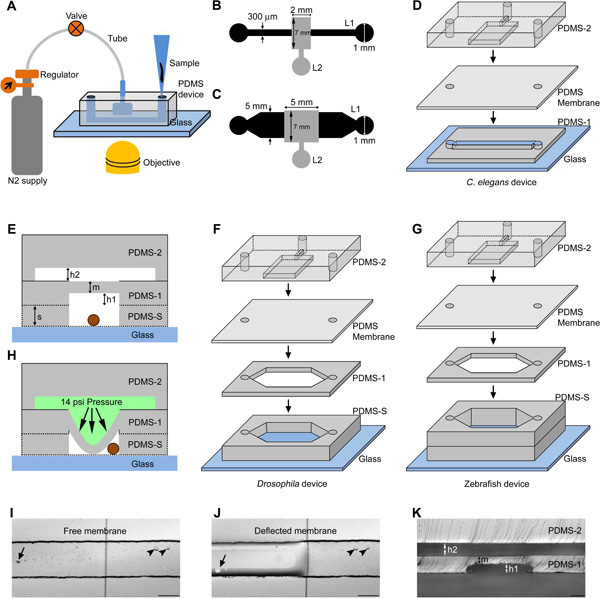
Figure 1. Schematic representation of PDMS microfluidic devices for genetic model organisms. (A) The organism is loaded using a micro tip into the flow channel and immobilized using compressed nitrogen gas controlled using a regulator and valve. The device is suitable for bright field/fluorescence imaging in an inverted microscope. The design consists of a 10 mm long flow channel (design I, L1) and a control channel (design II, L2) respectively for C. elegans (B) and Drosophila/zebrafish larvae (C). The dimensions are indicated on the design (B and C). (D, F, G) Schematic of various layers of PDMS (PDMS-1, PDMS-2, PDMS membrane, PDMS-S and Glass) present in a C. elegans, Drosophila and zebrafish immobilization device. (E) Schematic representation of a cross section of the device showing the bulk PDMS layer (PDMS-2), a spin coated PDMS layer (PDMS-1) to form a flexible membrane and a spacer PDMS layer (PDMS-S) to add height to the flow channel (for Drosophila/zebrafish device). The whole structure is bonded irreversibly to an optical grade glass cover slip to accommodate the organism (circle in brown). The schematic indicates height of the control channel 'h2', flow channel 'h1', punched spacer layer 's' and membrane thickness 'm'. (H) Indicates the membrane deflection towards the flow channel in the presence of liquid column under pressure in the control channel. Bright field images are shown of a free (I) and deflected membrane (J) under zero and 14 psi pressurized liquid column respectively. The arrow and arrow head indicate bubble under and out of the membrane in the flow channel respectively. (K) Cross sectional image of the C. elegans device taken at the location of the immobilization area. Scale bar is 50 μm (K) and 200 μm (I, J). (D, F, G) Schematics are not to scale. Click here to view larger figure.
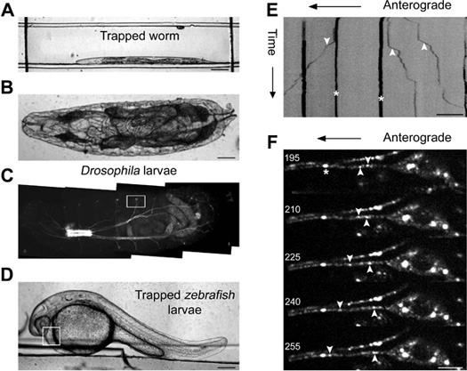
Figure 2. Imaging genetic model organisms immobilized in a microfluidic device. Bright field image of an immobilized C. elegans (A), a first instar Drosophila larvae (B) and a 30 hpf zebrafish larvae (D) in a PDMS microfluidic device. Kymograph analysis of time-lapse imaging of jsIs609, a C. elegans strain, expressing a mitochondrial matrix targeted GFP in an anterior lateral mechanosensory neuron (ALM) of a device immobilized animal (E). Mitochondria are classified as anterograde ('down' arrow head), retrograde ('up' arrow head) and stationary ('star' mark) in the kymograph. (C) Fluorescence image of an intact first instar Drosophila larva. The box indicates the location where high resolution time-lapse imaging of syt.eGFP transport is carried out in a cholinergic neuron. Montage of five frames acquired at 5 Hz with frame numbers indicated on each image and GFP marked cargo shown as anterograde, retrograde and stationary in the montage (F). The box in (D) indicates the area that was monitored for calculating rate of heartbeat of zebrafish larvae. Scale bar is 5 μm (F), 10 μm (E), 100 μm (A, B) and 200 μm (D).
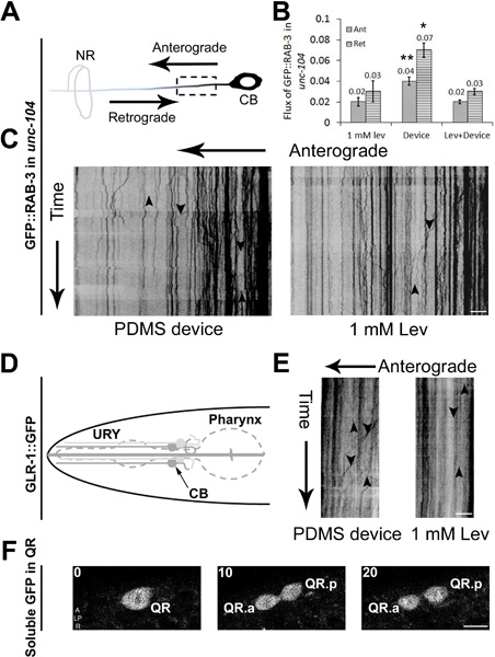
Figure 3. Cellular and sub-cellular imaging in C. elegans using PDMS microfluidic devices. (A) Schematic of an anterior lateral mechanosensory (ALM) neuron with the anterograde and retrograde directions marked. The dotted box shows the region imaged for axonal transport. 350 frames are acquired using a spinning disc confocal microscope at 5 fps with cell body (CB) on the right and nerve ring (NR) on the left. Data are analyzed using kymographs for animals immobilized in a device or using 1 mM levamisole (C). Cargo moving in anterograde and retrograde directions are shown using arrows pointing 'down' and 'up' respectively. (B) Anterograde and retrograde flux of particles observed in unc-104(e1265) animals in a 20 μm region of the ALM neuron over 350 time-lapse frames. (D) Schematic of an URY neuron used to image GFP marked glutamate receptors transport. 350 time-lapse frames are converted into kymographs that show cargo moving in the anterograde and retrograde directions in animals immobilized in PDMS device or using 1 mM levamisole (E). Time-lapse images acquired during Q neuroblast division and migration in early larval stages of C. elegans. (F) Three time-lapse frames that show QR undergoing division to form its daughter cells QR.a and QR.p. Scale bar is 5 μm (C, E and F). Data represented in (B) is mean ± SEM (n>4). Comparisons are made with respect to values obtained in anesthetic and denoted by * (p<0.05) and ** (p<0.005).
Discussion
PDMS microfluidic devices are optically transparent therefore can be used for high resolution in vivo imaging of any transparent/translucent model organism. Our design is suitable for high magnification spatio-temporal imaging of cellular and sub-cellular events in intact live animals. Microfabrication using soft lithography techniques allows easy manipulation of device dimensions for various sizes of model organisms. Devices of various sizes are fabricated for different stages of C. elegans, Drosophila larvae and zebrafish larvae. Devices with different heights of 40 μm and 80 μm in their flow layer channels show improved immobilization and better post-imaging health of both early (L1) and later (late L4) stages of C. elegans respectively. We achieve a 100% success rate in device fabrication for C. elegans and Drosophila/zebrafish without any defective devices. Devices can be used multiple times until the control channel is contaminated with dust particles or bacterial growth. Device immobilized C. elegans show greater cargo flux in both wild type and mutant animals when compared to anesthesized animals. Device immobilization eliminates the need for technically challenging dissection protocols especially for early developmental stages of Drosophila larvae 29.
Instantaneous immobilization protocols in PDMS microfluidic devices have an inherent advantage of reducing experimental time as compared to the typically longer exposure times required for externally applied anesthetics. All immobilized organisms return to normal locomotion within 5-10 min after the release of pressure on the deformable PDMS membrane. C. elegans are immobilized at the boundary of the flow channel and away from the central portion of the immobilization membrane. Animals immobilized in the middle of the flow channel show poor health post-immobilization and die within a day or two. Our microfluidic device has been used to keep L4 stage C. elegans immobilized for up to an hour under the membrane without affecting its health or subsequent development. Animals immobilized for shorter times (up to 10 min) could be trapped multiple times for imaging. For early developmental stages, C. elegans were immobilized with slightly lower pressure (7 psi) for longer term time-lapse experiments (~3 hr). Animals immobilized under the membrane post-release were left in the same device in the intervening time. These animals are comparable to wild type in both their development and general health. Adult C. elegans immobilized with lower pressure (7 psi) showed slow drift during high resolution time-lapse experiments and require complex analysis tools for transport analysis. However lower pressures were used to perform longer term studies such as Q neuroblast cell division/migration over ~3 hr or semi quantitative mitochondria transport characterization; processes that do not need complete immobilization. Thus lower pressures of immobilization can be used depending on the data set that needs to be collected.
Time-lapse imaging of L4 C. elegans shows saltatory motion of GFP marked mitochondria in the ALM neuron (strain jsIs609) as has been reported for neurons in other model systems 30-32. Some mitochondria in these neurons show bidirectional transport while the majority of them are stationary over the duration of the movie. In spite of the small differences in flux we continue using 14 psi immobilization pressure in case of C. elegans to obtain complete immobilization and avoid any drift during high resolution time-lapse imaging of axonal transport. We suggest using 14 psi in a general protocol and depending upon experimental needs this can be either increased or decreased. Animals took nearly the same time to return to normal locomotion from both lower and higher immobilization pressures and immobilized animals developed identically to those grown without immobilization.
The device when fabricated using larger dimensions with spacer layers can be used for bigger model organisms such as Drosophila and zebrafish larvae. Imaging of synaptotagmin.eGFP transport in intact first instar Drosophila sensory neurons shows active transport in both anterograde and retrograde directions. The average velocities measured in device immobilized larvae are higher compared to the values measured in dissected motor neurons 22. This difference may arise from faster acquisition of data in our experiments (5 hz v/s 1.1-1.4 hz), neuron-specific differences in organelle transport (sensory v/s motor neurons) and/or the effects due to dissection.
Our prior experiments were carried out exclusively in wild type animals 4, thus we determined whether imaging mutants in microfluidic devices was also advantageous. Time-lapse imaging of C. elegans L4 animals shows reduced flux of GFP::RAB-3 marked pre-synaptic vesicles in kinesin3/unc-104 mutants immobilized in 1.0 mM levamisole as compared to flux measurements obtained in animals immobilized using our PDMS device (Figure 3B). We have often observed and show an example (Figure 3C) that in mutants very little transport is observed if animals are immobilized using anesthetic concentrations that immobilize wild type animals. The numbers of vesicles moving in unc-104 animals is significantly higher when we use microfluidic devices. Anesthetized animals show similar transport characteristics when placed under 14 psi pressure applied to the PDMS membrane (Figure 3B). Similar observations have also been made in wild type animals 4. These data suggest that the increased flux is not likely to arise from immobilization under nitrogen but due to a protocol that was less damaging to the intra-cellular transport.
In principle, other events such as calcium dynamics and cell division can all be imaged in intact Drosophila/zebrafish larvae as well. Post-imaging recovery of device immobilized animals is less detrimental to organism viability 4 and thus such devices can also be used to perform long-term imaging of genetic model genetic organisms for events that occur over longer time scales.
Disclosures
No conflicts of interest declared.
Acknowledgements
We thank Dr. Krishanu Ray for Drosophila stocks, Tarjani Agarwal for maintaining a Drosophila cage, Peter Juo for nuIs25 and CGC for C. elegans strains. SPK made jsIs609 in Michael Nonet's laboratory. We thank Arpan Agnihotri (BITS Pilani) for his help in time-lapse imaging of mitochondria transport of jsIs609 animals in microfluidic devices. We are grateful to Dr. Vatsala Thirumalai and Surya Prakash for providing us with zebrafish embryos. We thank Dr. Krishna and CIFF at NCBS for use of the spinning disc confocal microscope supported by the Department of Science and Technology- Centre for Nanotechnology (No. SR/55/NM-36-2005). We also thank Kaustubh Rau, V. Venkatraman and Chetana Sachidanand for discussions. This work was funded by the DBT post-doctoral fellowship (S.M.), DST fast-track scheme (S.M.) and a DBT grant to (S.P.K.). S.A. was supported by DST and CSIR grants to SPK.
Materials
| Name | Company | Catalog Number | Comments |
|---|---|---|---|
| Silicon wafers | University wafer | 150 mm (100) Mech Grade SSP Si | |
| Clewin Software | WieWeb software | Version 2.90 | |
| Laser plotter | Fine Line Imaging | 65,024 DPI | |
| HMDS | Sigma-Aldrich | 440191-100ML | |
| SU8 | Microchem | SU8-2025, SU8-2050 | |
| Developer | Microchem | SU8 Developer | |
| Silane | Sigma-Aldrich | 448931-10G | |
| PDMS | Dow corning | Sylgard 184 | |
| UV lamp | Oriel | 66943 | 200W Hg Oriel Light |
| Hot air oven | Ultra Instruments | Custom made | Set at 50 °C |
| Hot plate | IKA Laboratory Equipment | 3810000 | http://www.ika.com |
| Plasma cleaner | Harrick Plasma | PDC-32G | |
| Spinner | Semiconductor Production Systems | SPIN150-NPP | www.SPS-Europe.com |
| Glass cover slip | Gold Seal | 22 X 22 mm, No. 1 thickness | |
| C. elegans | Caenorhabditis Genetics Center (CGC) | e1265, ayIs4 | |
| Drosophila | Bloomington | P{chaGAL4}/cyo, UAS-syt.eGFP | |
| Zebrafish | Indian wild type | Wild type | |
| Tygon tube | Sigma | Z279803 | |
| Micro needle | Sigma | Z118044 | Cut into 1 cm pieces |
| 3-way stopcock | Sigma | S7521 | |
| Harris puncher | Sigma | Z708631 | |
| Compressed nitrogen gas | Local Gas supplier | Use a regulator to control the pressure | |
| Stereo microscope | Nikon | SMZ645 | |
| Confocal microscope | Andor Olympus | Yokogawa spinning disc confocal microscope | |
| ImageJ | National Institutes of Health | www.rsbweb.nih.gov/ij | Java based image processing program |
References
- Whitesides, G. M., Ostuni, E., Takayama, S., Jiang, X., Ingber, D. E. Soft lithography in biology and biochemistry. Annu. Rev. Biomed. Eng. 3, 335-373 (2001).
- Guo, S. X. Femtosecond laser nanoaxotomy lab-on-a-chip for in vivo nerve regeneration studies. Nat. Methods. 5, 531-533 (2008).
- Gilleland, C. L., Rohde, C. B., Zeng, F., Yanik, M. F. Microfluidic immobilization of physiologically active Caenorhabditis elegans. Nat. Protoc. 5, 1888-1902 (2010).
- Mondal, S., Ahlawat, S., Rau, K., Venkataraman, V., Koushika, S. P. Imaging in vivo neuronal transport in genetic model organisms using microfluidic devices. Traffic. 12, 372-385 (2011).
- Chung, K., Crane, M. M., Lu, H. Automated on-chip rapid microscopy, phenotyping and sorting of C. elegans. Nat. Methods. 5, 637-643 (2008).
- Allen, P. B. Single-synapse ablation and long-term imaging in live C. elegans. J. Neurosci. Methods. 173, 20-26 (2008).
- Chronis, N., Zimmer, M., Bargmann, C. I. Microfluidics for in vivo imaging of neuronal and behavioral activity in Caenorhabditis elegans. Nat. Methods. 4, 727-731 (2007).
- Rohde, C. B., Zeng, F., Gonzalez-Rubio, R., Angel, M., Yanik, M. F. Microfluidic system for on-chip high-throughput whole-animal sorting and screening at subcellular resolution. Proc. Natl. Acad. Sci. U.S.A. 104, 13891-13895 (2007).
- Hulme, S. E., Shevkoplyas, S. S., Apfeld, J., Fontana, W., Whitesides, G. M. A microfabricated array of clamps for immobilizing and imaging C. elegans. Lab Chip. 7, 1515-1523 (2007).
- Zeng, F., Rohde, C. B., Yanik, M. F. Sub-cellular precision on-chip small-animal immobilization, multi-photon imaging and femtosecond-laser manipulation. Lab Chip. 8, 653-656 (2008).
- Chokshi, T. V., Ben-Yakar, A., Chronis, N. CO2 and compressive immobilization of C. elegans on-chip. Lab Chip. 9, 151-157 (2009).
- Krajniak, J., Lu, H. Long-term high-resolution imaging and culture of C. elegans in chip-gel hybrid microfluidic device for developmental studies. Lab Chip. 10, 1862-1868 (2010).
- Goodman, M. B., Hall, D. H., Avery, L., Lockery, S. R. Active currents regulate sensitivity and dynamic range in C. elegans neurons. Neuron. 20, 763-772 (1998).
- Snow, J. J. Two anterograde intraflagellar transport motors cooperate to build sensory cilia on C. elegans neurons. Nat. Cell Biol. 6, 1109-1113 (2004).
- Lewis, J. A., Wu, C. H., Berg, H., Levine, J. H. The genetics of levamisole resistance in the nematode Caenorhabditis elegans. Genetics. 95, 905-928 (1980).
- Richmond, J. E., Jorgensen, E. M. One GABA and two acetylcholine receptors function at the C. elegans neuromuscular junction. Nat. Neurosci. 2, 791-797 (1999).
- Badre, N. H., Martin, M. E., Cooper, R. L. The physiological and behavioral effects of carbon dioxide on Drosophila melanogaster larvae. Comp. Biochem. Physiol. A. Mol. Integr. Physiol. 140, 363-376 (2005).
- Stiernagle, T. Maintenance of C. elegans. WormBook. , 1-11 (2006).
- Westerfield, M. The zebrafish book. A guide for the laboratory use of zebrafish (Danio rerio). , 4th edn, Univ. of Oregon Press. Eugene. (2000).
- Henn, K., Braunbeck, T. Dechorionation as a tool to improve the fish embryo toxicity test (FET) with the zebrafish (Danio rerio). Comp. Biochem. Physiol. C. Toxicol. Pharmacol. 153, 91-98 (2011).
- Fatouros, C. Inhibition of tau aggregation in a novel Caenorhabditis elegans model of tauopathy mitigates proteotoxicity. Hum. Mol. Genet. , (2012).
- Barkus, R. V., Klyachko, O., Horiuchi, D., Dickson, B. J., Saxton, W. M. Identification of an axonal kinesin-3 motor for fast anterograde vesicle transport that facilitates retrograde transport of neuropeptides. Mol. Biol. Cell. 19, 274-283 (2008).
- Craig, M. P., Gilday, S. D., Hove, J. R. Dose-dependent effects of chemical immobilization on the heart rate of embryonic zebrafish. Lab. Anim. (NY). 35, 41-47 (2006).
- Pardo-Martin, C. High-throughput in vivo vertebrate screening. Nat. Methods. 7, 634-636 (2010).
- Stainier, D. Y., Lee, R. K., Fishman, M. C. Cardiovascular development in the zebrafish. I. Myocardial fate map and heart tube formation. Development. 119, 31-40 (1993).
- Hall, D. H., Hedgecock, E. M. Kinesin-related gene unc-104 is required for axonal transport of synaptic vesicles in C. elegans. Cell. 65, 837-847 (1991).
- Kumar, J. The Caenorhabditis elegans Kinesin-3 motor UNC-104/KIF1A is degraded upon loss of specific binding to cargo. PLoS Genet. 6, e1001200(2010).
- Ou, G., Vale, R. D. Molecular signatures of cell migration in C. elegans Q neuroblasts. J. Cell. Biol. 185, 77-85 (2009).
- Levitan, E. S., Lanni, F., Shakiryanova, D. In vivo imaging of vesicle motion and release at the Drosophila neuromuscular junction. Nat. Protoc. 2, 1117-1125 (2007).
- Morris, R. L., Hollenbeck, P. J. The regulation of bidirectional mitochondrial transport is coordinated with axonal outgrowth. J. Cell. Sci. 104, 917-927 (1993).
- Louie, K., Russo, G. J., Salkoff, D. B., Wellington, A., Zinsmaier, K. E. Effects of imaging conditions on mitochondrial transport and length in larval motor axons of Drosophila. Comp. Biochem. Physiol. A. Mol. Integr. Physiol. 151, 159-172 (2008).
- Pilling, A. D., Horiuchi, D., Lively, C. M., Saxton, W. M. Kinesin-1 and Dynein are the primary motors for fast transport of mitochondria in Drosophila motor axons. Mol. Biol. Cell. 17, 2057-2068 (2006).
Reprints and Permissions
