Microscopy is a method that is widely used to image the detailed structure of samples. Optical microscopes, which focus light through a series of lenses to magnify samples, have been in use for centuries with the first compound microscope appearing in the 17th century. During that time, Antonie van Leeuwenhoek was the first to observe bacteria, yeast, red blood cells, and circulation in capillary vessels, making significant scientific contributions and paving the way for microscopic advancements.
Optical microscopes are still widely used today in research and clinical settings for medical diagnosis. However, in the last 60 years, confocal microscopy has emerged which illuminates the sample through a pinhole to increase optical resolution and contrast.
This video will illustrate the operating principles of optical and confocal microscopy, demonstrate how high resolution images are analyzed, and discuss several applications of microscopy in the field of biomedical engineering.
Let us begin by discussing the fundamentals of confocal microscopy. Optical microscopy is based on the principle of focusing light onto a sample to image its detailed structure. A microscope is formed of two magnification components; the objective lens, which focuses a real image of an object, and the eyepiece, which focuses a magnified virtual image before it is received by the eye. The total magnification is attained by multiplying the magnifications of these two lenses.
The focusing of light gives a specified plane of focus where the magnification and the lamp light all meet at the same point, which gives the best resolution in the image. When outside of the focal plane, the area of illumination is larger and light beams interfere from other parts of the sample, causing the image to be blurry. Where light microscopes illuminate and image the entire sample in view, a confocal microscope utilizes a pin hole between the sample stage and the detector so that only a small light beam is focused at one narrow depth at a time.
Consequently, the only visible area of the sample, is the in-focus point, providing a well resolved image. However, with higher resolution, only a small portion of this sample is imaged at a time. By moving the sample in the X-Y plane, a raster scan of its surface can be performed. For each point of the scan, the focus is optimized by adjusting the Z height to access different focal planes. This ensures a maximal resolution point by point of the image sample.
Now let’s use these principles of microscopy and image resolution to image a mouse brain using both a confocal, and optical microscope.
Having reviewed the main principles of microscopy, let’s now perform a measurement using a confocal microscope. First, turn on the microscope at the computer work station. Then load the sample onto the stage and center it beneath the lens. Now open the imaging software and select create new job. Go to topography’s column and choose the assistant button. Select the lowest magnification, which for this microscope, is 2.5x. Then use the 3D microscope manipulator to adjust the Z position of the sample and bring the sample into focus. Push the button on the side so that a blue light appears around the edges. This allows for finer Z motion and focus. Now capture an overview image.
Slowly increase the lens magnification and adjust the light intensity and focus to obtain the desired magnification. Use the 3D manipulator in the X and Y directions to select different areas of interest on the sample. Once an image is taken at low magnification, press next to take a reference point. Use either the default reference point, or specify a new one in the corner of the sample, then press next. Now gradually change the objective to the desired resolution for the sample. For this sample, a 20x objective is used to visualize the cells in mouse brain tissue. Make sure that there is room to decrease the working distance.
To define the distance to collect slices, first go to the measuring range definition page and use the 3D manipulator to finally adjust the sample in the Z direction. Click set last when the top of the sample is in focus and click set first when the bottom of the sample is in focus. Make sure that the number of calculated slices does not exceed 1,000 or the program will fail. Verify that there are no red pixels, which indicates that the intensity of light is oversaturated.
Finally, press done to take the tomography image. When the tomography software opens, select the studies tab to view the data in 3D and take 2D and 3D measurements.
Now lets take an image using a digital optical microscope. First, turn on the microscope and open the imaging software. Then load the sample onto the stage and center it beneath the lens. When the imaging software is open, select a job from the list of templates or choose free examination. Then, acquire an overview image that shows the entire stage. Use the controller to change the focus and the image position.
Once the acquisition is complete, place a coordinate system on the image. The default coordinate system is in the middle of the stage. For more flexibility, the coordinates can be changed manually.
Then name the sample and select the camera button. Press the live button as you navigate the sample and move the focus downwards until the sample is clearly in focus. If needed, use the lighting and aperture tab to adjust the lighting. Then acquire an image of the sample.
Use the tools under the image optimization panel, such as the tilt of the lens, the lighting levels on the sample, and the brightness and contrast in the image to optimize the image to the desired crispness. Now tap the pencil tool to perform measurements. Use the distance and area tools to measure the size of the cells on the sample.
Finally, go to the results workflow tab and configure the layout of the report. Tap the save button to save the job for further analysis.
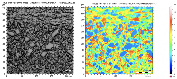
Now lets analyze the images of a mouse brain that were taken with confocal and digital optical microscopes. The confocal image at 50x magnification is high resolution and provides deep focus with varying depth levels of information.
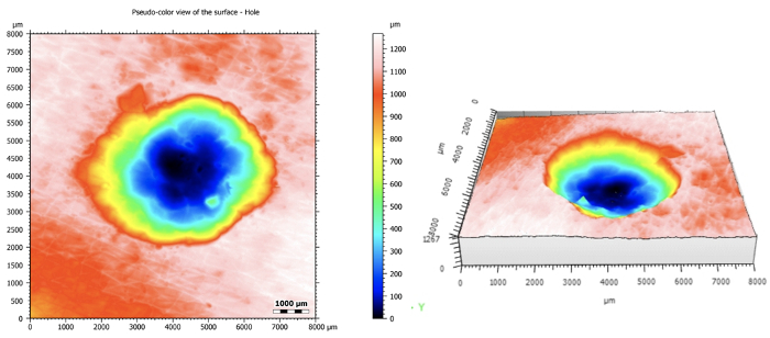
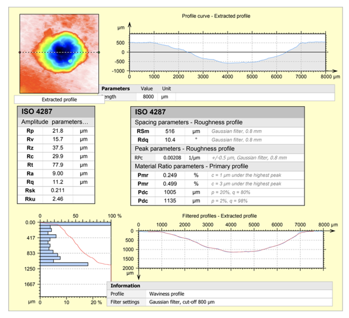
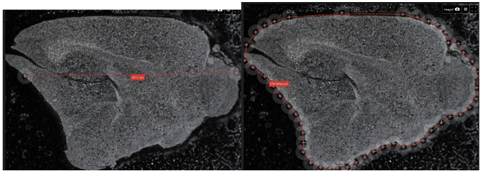
On the tomographical map, the hight of this sample ranges from one to nine microns. Characteristics such as the amplitude, roughness profile, and curve parameters can be further analyzed. However, the entire slide of the sectioned brain tissue can be imaged using a digital optical microscope.
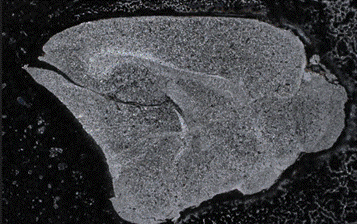
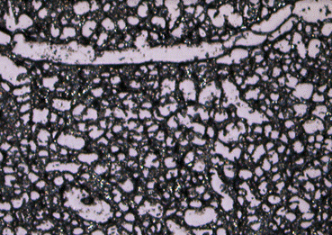
Zooming in on a section shows more details of the sample but at a much lower resolution than obtained with confocal microscope. This sample was obtained at 300x magnification. Dedicated software offers tools to measure cross sectional dimensions, such as the diameter, as well as to calculate the internal area of the section.
Digital, optical, and confocal microscopy are standard tools used in various biomedical applications. Scanning laser ophthalmoscopy or SLO is a non-invasive imaging technique that is extensively used in clinical ophthalmology to diagnose and monitor the development of retinal diseases.
SLO produces high contrast stereoscopic images that visualize the microglia. The resident macrophages of the retina, that are involved in several retinal diseases. Confocal microscopy is also used in live cell imaging which allows researchers to visualize microscopic biological cell function in real time.
This technique is used to study cell migration and proliferation and protein dynamics among others. Here, transmembrane receptors and lysosomes were labeled with fluorescent dyes and their colocalization was analyzed using timelapse imaging to investigate receptor internalization.
You’ve just watched JoVE’s introduction to digital, optical, and confocal microscopy. You should now understand the principles of microscopy and image resolution, how to operate both optical and confocal microscopes to image biological samples, and several applications of their use in the biomedical engineering field.
Thanks for watching.