1. Alginate Electrodeposition
- Connect a power supply to the custom fabricated electrodes via patch cords using alligator clips. An indium tin oxide (ITO) covered glass slide will act as the anode (working electrode) and platinum foil will serve as the cathode (counter-electrode). Position the electrodes so the ITO surface to be functionalized opposes the counter electrode and is positioned either vertically to be dipped into a solution or horizontally such that the deposition solution is contained on the surface.
- Prepare an alginate deposition solution by mixing 1% alginate and 0.5% CaCO3 (by weight) in distilled water and then autoclaving the solution. It is recommended to continuously stir the solution when not in use.
- Submerge both electrodes into the deposition solution. The alginate used may be fluorescently labeled with FluoroSpheres (Invitrogen), as per Cheng et al. 14, to allow for fluorescence imaging of the resulting film.
- Apply a constant current density (3 A/m2) for 2 minutes; voltage will shift within the range of 2-3 V.
- Disconnect the electrode and remove the non-deposited solution. Gently rinse the film with NaCl (0.145 M) to remove superfluous alginate.
- Incubate the film briefly (~1 min) in CaCl2 (0.1 M) to strengthen the gel. Rinse with NaCl (0.145 M) and incubate in a desired solution supplemented with CaCl2 (1 mM).
- Image using a fluorescence microscope (Figure 1B).
2. Codeposition of Communicating Cell Populations in Alginate
- A signal-sender cell culture (W3110 wt E. coli), grown in LB media, and a signal-receiver cell culture (MDAI2 + pCT6-lsrR–ampr + pET-dsRed–kanr), grown in LB media + 50 μg/mL each of kanamycin and ampicillin, must be grown up overnight and re-inoculated for growth to an optical density (at 600 nm) of 1. Adjust optical density of the receiver cell culture to 0.4-0.6 with LB before use.
- Prepare a deposition solution of 2% alginate and 1% CaCO3, and mix with each cell culture in a 1:1 ratio to a final concentration of 1% alginate, 0.5% CaCO3, with the cells diluted to a density of about half the culturing density.
- Use a glass slide patterned with two ITO electrodes contained by a polydimethylsiloxane (PDMS) well (prepared according to Sylgard instructions and cut to desired size) and a platinum counter electrode. Connect one ITO electrode to a power supply with the platinum as described in Procedure 1 (Alginate electrodeposition).
- Immerse the electrodes in a deposition solution containing the receiver cells. Set the power supply to a constant current at a density of 3 A/m2, where the surface area dimension is defined by the single electrode on which deposition will occur.
- Apply the current for 2 minutes to allow for codeposition of the cells in the alginate matrix.
- Rinse the film as described in Step 1.5.
- Switch the anodic connection to the second, adjacent, ITO electrode.
- Repeat the deposition procedure (Steps 2.4 – 2.7), but this time introducing the solution containing the sender cells.
- Incubate the 2-electrode chip containing codeposited cells and calcium-alginate overnight at 37 °C in phosphate buffered saline (PBS) supplemented with 10% LB media and 1 mM CaCl2.
- After incubation, image using a fluorescence microscope (Figure 2B).
3. Chitosan Electrodeposition
- Connect the power supply to the electrodes via alligator clips. A gold coated silicon chip will act as the cathode (working electrode) and a platinum foil will serve as the anode (counter-electrode). Position the gold electrode’s surface so that it opposes the counter electrode and both are positioned either vertically to be dipped into a solution or horizontally such that the deposition solution is contained on the surface.
- Prepare a chitosan solution by mixing chitosan flakes into water and slowly adding 2 M HCl to dissolve the polysaccharides (final pH 5.6), making sure to follow the procedure outlined by Meyer et al. 15.
- Place the electrodes into a chitosan solution (0.8 %), completely submerging the desired area for deposition. The chitosan used can be fluorescently labeled with 5-(and-6)-carboxyrhodamine 6G succinimidyl ester (Invitrogen), as per Wu et al. 8, to image the electrodeposited film by fluorescence microscopy.
- Apply a constant current density (4 A/m2) for 2 minutes. Voltage will shift within the range of 2-3 V. Calculate the current density as a function of the gold surface area of the working electrode exposed to the deposition solution.
- Rinse the electrode with DI water to remove superfluous chitosan. The chip can be stored in water or PBS (10 mM, pH 7.0).
- Image using a fluorescence microscope (Figure 3C).
4. Electrochemical Transduction with a Functionalized Chitosan Film
- Codeposit chitosan and glucose oxidase (GOx) from a solution (1% chitosan, 680 U/mL GOx, pH 5.6) at a current density of 4 A/m2 onto a patterned electrode according to Procedure 3 (Chitosan electrodeposition). A chitosan film entrapped in GOx will be generated.
- Attach the treated electrode to a three-electrode system as the working electrode, a platinum wire as the counter-electrode and Ag/AgCl as the reference electrode, as described in Figure 4A.
- Immerse the electrodes into a phosphate buffer solution (0.1 M, pH 7.0) containing NaCl (0.1 M).
- Electrochemically conjugate the protein to the chitosan film by applying a constant voltage (0.9 V) for 60s using chronoamperometry10.
- Place the chip in phosphate buffer (0.1 M, pH 7.0) and wash for 10 minutes on an orbital shaker to remove any unreacted NaCl and unconjugated GOx.
- Re-attach to the three-electrode system as described in step 4.2 and immerse into a solution of 5 mM glucose. Using cyclic voltammetry, sweep the potential in a positive direction to 0.7 V. Use a control film containing no glucose oxidase as a comparison for the amount of oxidation seen in the sweep (Figure 4B).
- Remove the electrodes from the glucose solution and rinse with phosphate buffer (0.1 M, pH 7.0) then place the electrodes into a 10 mL beaker containing 8 mL of phosphate buffer (0.1 M, pH 7.0). Bias the GOx-functionalized chip to 0.6 V to serve as the working electrode (Figure 4C).
- Add aliquots of glucose to the buffer (each aliquot increases the glucose concentration by 4 mM).
- Generate a standard curve between the steady state current and the glucose concentration for the GOx-functionalized chitosan film.
5. Protein Functionalization Using Enzymatic Assembly
- Use a glass slide patterned with an adjacent gold and ITO electrode contained within a PDMS well. Bias the gold electrode with a cathodic potential to electrodeposit chitosan as shown previously. Rinse film briefly in DI water and then PBS by pipette.
- Add a solution of 3 μM blue fluorescently labeled “AI-2 Synthase” 16 (using a DyLight labeling kit) + 100 U/mL Tyrosinase in PBS.
- Incubate for 1 h at room temperature, then rinse the film with PBS.
- Apply an anodic potential to the ITO electrode to codeposit an alginate deposition solution containing receiver cells (as prepared in steps 2.1-2.2). Follow steps 2.3-2.6 of Procedure 2 (Codeposition of cell populations in alginate).
- To generate the transmitted signal (AI-2) enzymatically, after rinsing the films add a solution of 500 μM S-adenosyl homocysteine (SAH) in PBS, supplemented with 10% LB media and 1mM CaCl2. Cover the electrodes to prevent evaporation of the solution and incubate overnight at 37 °C. This will allow for a receiver cell response by generating a red fluorescent protein (dsRed).
- Adjacent electrodes may be imaged with fluorescence microscopy by adjusting the filters to capture the blue fluorescence of the AI-2 Synthase and red fluorescence expressed by the codeposited receiver cells (Figure 5B).
6. Representative Results
Imposed electrical signals can create localized microenvironments (e.g., fields and gradients) near an electrode surface and these stimuli can trigger the self-assembly of polysaccharides such as alginate and chitosan to deposit as a hydrogel film on the electrode surface. Because this sol-gel transition occurs at the electrode surface, the resulting film is electroaddressed, with its geometry matching the electrode pattern (Figures 1B, 3C). Biocompatible films such as alginate and chitosan provide surfaces that can be functionalized with biological components. Using alginate, unique cell populations have been codeposited at separate addresses. Evidence of their electroaddressment is observed upon interaction between the sender and receiver cell population. The molecule autoinducer-2 (AI-2) diffuses from the sender cells and is taken up by the receiver cells, resulting in expression of the dsRed red fluorescent protein (Figure 2A). In Figure 2B, red fluorescence is observed only at the electrode where receivers are addressed.
The amine groups present on chitosan provide it with the pH responsiveness required for electrodeposition as well as a surface suitable for functionalization. We utilized these unique properties by electrochemically conjugating the biosensing enzyme glucose oxidase (GOx) to electrodeposited chitosan films. This enzyme then provides the ability for detection of glucose through an enzymatic reaction (Figure 4A) producing hydrogen peroxide which can then be electrochemically oxidized to produce an output current. In this way, a chemical signal can be transduced to electrical. Figure 4B shows that films in which GOx was electrochemically conjugated produce a strong anodic signal in the presence of glucose as opposed to those films containing no GOx. These results indicate GOx can be assembled onto a deposited chitosan film and will retain catalytic activity. Furthermore, Figure 4C shows a step-increase in anodic current produced in response to increasing glucose concentrations. The standard curve also present in Figure 4C shows that the step-increases proceeded in a near linear fashion dependent on the amount of glucose added. These results show that the enzyme also retains its sensitivity to increasing glucose concentrations upon conjugation to the chitosan film. The lower limit of detection was not studied here as it has been previously characterized for this system in the work of Meyer et. al.
We also have demonstrated the covalent immobilization of an enzyme of interest, engineered to contain a custom penta-tyrosine tag, to chitosan in an enzymatically-controlled manner. Specifically, this process is mediated by the enzyme tyrosinase. As depicted by the scheme in Figure 5A(upper), an enzyme, AI-2 Synthase includes a penta-tyrosine tag. Tyrosinase acts on the tyrosine tag, oxidizing the residues’ phenol groups to O-quinones, which then covalently bind to chitosan’s amines. Evidence of chitosan film functionalization with the AI-2 Synthase by tyrosinase assembly is observed in Figure 5B, where the AI-2 Synthase has been fluorescently labeled blue. Because AI-2 Synthase generates AI-2 from the substrate S-adenosyl homocysteine (SAH) in the same way as the sender cells, its proximity to codeposited receiver cells in the presence of SAH also causes the receiver cells to fluorescently respond by expressing dsRed (Figure 5A(lower)). Red fluorescence of the receiver cells (Figure 5B) again demonstrates interaction between addresses due to the diffusion of AI-2 from one to the other, and further indicates that enzymes immobilized to chitosan retain activity once covalently bound.
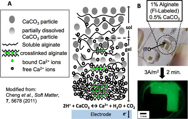
Figure 1. Alginate electrodeposition. (A) Mechanism of alginate electrodeposition: As an electrode is anodically biased, water electrolysis occurs at its surface, generating a localized low pH. Calcium carbonate particles react with the surplus of protons, releasing calcium cations as the particles dissolve. In the presence of alginate polymer chains, the ions become chelated in an “eggbox” network, forming a crosslinked hydrogel at the electrode. As the distance from the electrode increases, alginate has a greater tendency to remain in solution due to the reduced presence of calcium ions. (B) An L-shaped patterned ITO electrode was used to electrodeposit alginate. A PDMS well was fixed to the electrode to contain a green fluorescently-labeled alginate (1%) and CaCO3 (0.5%) deposition solution. After electrodepositing for 2 min. at a current density of 3A/m2, the electroaddressed alginate hydrogel was imaged by fluorescence microscopy.
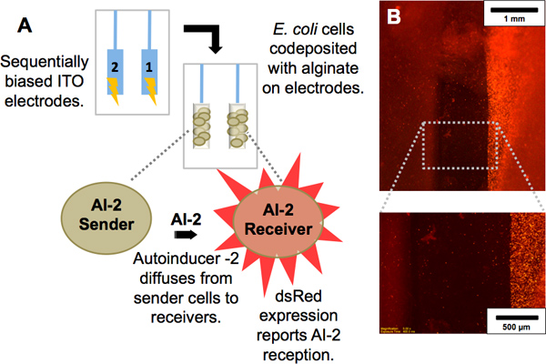
Figure 2. Codeposition of cell populations. (A) Scheme showing interaction between two E. coli strains: One population produces autoinducer-2 (AI-2), a signaling molecule, and is termed “AI-2 sender.” The other population, termed “AI-2 receiver,” is a reporter of AI-2; upon receipt of AI-2 by diffusion from the sender, it expresses the red fluorescent protein dsRed. (b) Red fluorescence image of electrode pair with the AI-2 sender population codeposited with alginate on the left electrode and AI-2 receiver population codeposited with alginate on right electrode. Magnified view demonstrates the dsRed expression of only the AI-2 receivers.
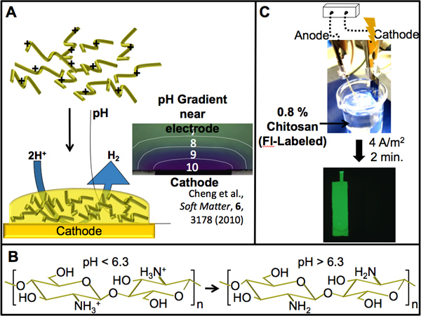
Figure 3. Chitosan electrodeposition. (A) Scheme showing the pH-dependent electrodeposition of chitosan. Water electrolysis at a cathodically biased electrode causes a localized high pH (shown by a localized color change of a pH indicator dye near the cathode in micrograph) which stimulates the sol-gel transition of chitosan in this region. (B) The amines present on chitosan give it pH-responsive properties. Above a pH of 6.3 (pKa of chitosan) the amines are deprotonated, facilitating a transition from its protonated soluble form to its insoluble gel form. (C) A patterned gold electrode was used to electrodeposit chitosan. The electrode, connected cathodically to the power supply, was immersed into a green fluorescently-labeled chitosan (0.8%) deposition solution. After electrodepositing for 2 min. at a current density of 4 A/m2, the electroaddressed chitosan film was imaged by fluorescence microscopy.
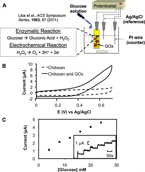
Figure 4. Electrochemical transduction with a functionalized chitosan film. (A) Schematic showing the set-up of a three electrode system. Functionalized chitosan film serves as the working electrode, a platinum wire as the counter electrode and Ag/AgCl as the reference electrode. Electrochemical transduction of glucose proceeds through the enzymatic and electrochemical reactions shown where produced hydrogen peroxide can be oxidized and detected at the working electrode. (B) Cyclic voltammagram (CV) at electrode with a chitosan film containing electrochemically conjugated glucose oxidase (GOx) shows a strong anodic signal in a 5 mM glucose solution. A film containing no GOx served as a control and displayed no signal in the same solution. (C) A standard curve between anodic current and the glucose concentration displays a near linear relationship (each aliquot increased the glucose concentration by 4 mM and also increased the current amplitude in the inset graph in a step-wise manner).
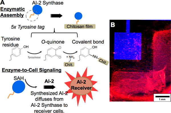
Figure 5. Protein functionalization using enzymatic assembly. (A, upper) Scheme showing tyrosine-tagged “AI-2 Synthase” being covalently tethered to a chitosan film by tyrosinase assembly. The tyrosine residues become oxidized to O-quinones by tyrosinase action and may react with amine groups on the chitosan film, forming a covalent bond. (A, lower) The AI-2 Synthase generates AI-2 from a substrate (SAH); the receiver cells report the generated AI-2 by dsRed fluorescence expression. (B) Fluorescence images showing a chitosan film on gold, functionalized with blue-labeled AI-2 Synthase. Adjacently, AI-2 receiver cells are codeposited with alginate on ITO. After addition of the enzymatic substrate to the well and incubation, the AI-2 receiver cells express dsRed.