All animal handling and procedures described herein were performed in accordance with a protocol approved by the National Institute of Neurological Disorders and Stroke Animal Care and Use Committee. Brains were collected from common marmosets (Callithrix jacchus) induced to develop EAE.11 Brains were stored in 10% formalin for between 3 weeks and one year after euthanasia by transcardial perfusion of 4% paraformaldehyde.
1. Postmortem MRI Preparation and Acquisition
2. Extracting Brain Surface: Mipav 7.2
3. Selecting Slice Locations: Mipav 7.2
4. Creating MRI Blade Map: Mipav 7.2
5. Importing Brain and Blade Gap Surfaces: Netfabb Professional
6. Editing Brain Contours: Meshmixer
7. Creating the Brain Slicer Box: Netfabb Professional
8. Printing the Brain Slicer Box on the Ultimaker 2
9. Cutting the Brain
10. Removing Overhangs in Brain Box (Supplementary section)
11. Marmoset Brain MRI Cradle for Additional Scanning
The workflow of this method is summarized in Figure 1. Once the brain is sliced, a visual comparison between the MR images and pictures of the superficial surfaces of the slabs shows a good orientation match across multiple slabs (Figure 2). After the slabs are embedded in paraffin, they are sectioned on a microtome and stained. A more thorough comparison between the high resolution postmortem MRI and the stained histology sections demonstrates an accurate and consistent match across all the structures of the marmoset brain (Figure 3).
In this animal model of MS, the animals develop white matter lesions spread throughout the cerebral white matter. These lesions can be detected noninvasively by performing MRI. Figure 4 demonstrates the ability of this technique to elucidate the pathological substrate of the MRI findings. Small lesions detected on in vivo MRI can be tracked on both postmortem MRI and histology. As shown in the insets, demyelination within the lesions is one of the main components driving the MR signal change (hyperintensity compared to surrounding tissue). The histology and postmortem MRI can also show lesions missed on in vivo MRI (Figure 4).
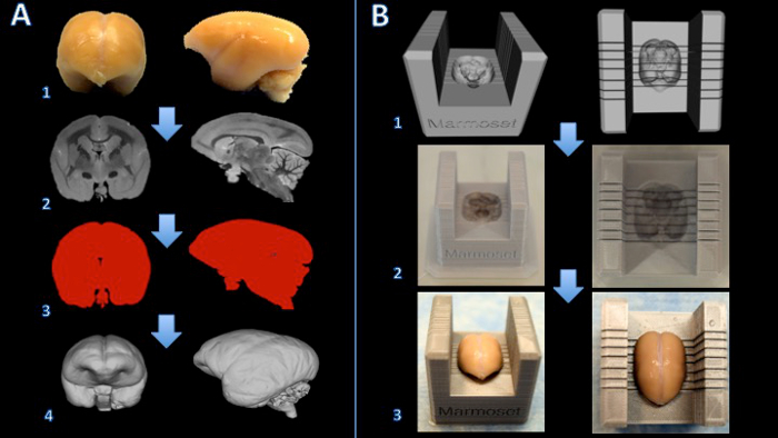
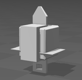
Figure 1. Workflow for creating a marmoset brain slicer box. The brain is fixed with formalin (A1) and a T2-weighted MRI is acquired with isotropic voxels of 150 µm per edge (A2). Images are processed and thresholded to create a binary mask (A3). The surface is then rendered in 3D modeling software (A4). A Boolean subtraction between a slicer template and the brain model creates a digital model of the brain slicer (B1). The brain slicer box is printed on a 3D printer (B2). The brain is then placed firmly in the slicer box for cutting (B3). Please click here to view a larger version of this figure.
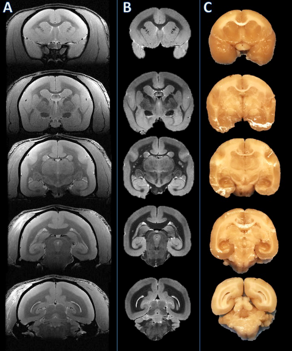
Figure 2. From left to right: In vivo MRI, postmortem MRI, and tissue slab photograph. Slicing planes were established based on the postmortem MRI (B) and visually compared to the corresponding in vivo MRI slice (A). The brain was then cut, and the resulting slabs were found to be consistent (C). Please click here to view a larger version of this figure.
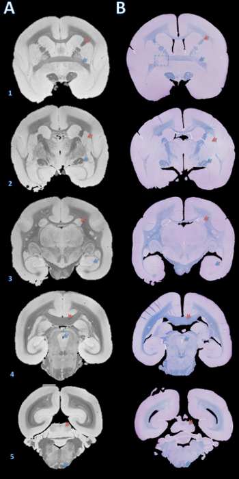
Figure 3. High-resolution postmortem MRI and histology section matching. Slabs were embedded in paraffin, cut with a microtome into 4 µm sections, and stained with fast blue and cresyl violet (B). The sections were then visually matched with the 100 µm T2*-weighted MRI based on brain structures (A). Details for acquiring this image are in the supplementary section of the protocol and Table 1. Brain structures: (1) red arrow = internal capsule, blue arrow = anterior commissure; (2) red arrow = putamen, blue arrow = optic tract; (3) red arrow = caudate, blue arrow = hippocampus; (4) red arrow = corpus callosum, blue arrow = cerebral aqueduct; (5) red arrow = inferior colliculus, blue arrow = pyramidal tract. The dashed box in B1 indicates a slice where, either during brain cutting or paraffin embedding, an error caused a slight rotation about the Y axis, leading to mismatch of the anterior commissure on the left. Please click here to view a larger version of this figure.
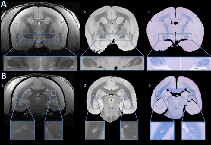
Figure 4. Tracking lesions from in vivo MRI to histology section. The in vivo MRI showed no convincing evidence of abnormal hyperintensity signal to suggest lesions in either optic tract (A1). However, the high resolution postmortem MRI shows clear hyper intense lines in both optic tracts (A2). The fast blue/cresyl violet stain of a 4 µm histology section shows that the hyperintense areas seen on the ex vivo MRI are demyelinated (A3). In the cerebral white matter, the in vivo MRI shows subtle hyperintensity bilaterally (B1, enlarged in the insets). The hyperintense areas are more obvious on the high resolution postmortem MRI (B2). The LFB stain of a 4 µm histology section shows that these areas are demyelinated (B3). After comparison with the baseline in vivo MRI and a hemotoxylin-and-eosin stain, the right side was determined to be an anatomical abnormality, not a demyelinated lesion. Please click here to view a larger version of this figure.
Supplemental code files. Brain_Slicer_Parts_Marmoset.stl: Please click here to download this file. Brain_Slicer_Parts_Human.stl: Please click here to download this file. Cap_Insert.stl: Please click here to download this file.
7T/30cm USR AVIII Bruker MRI | Bruker Biospin | ||
38 mm Bruker Biospin volume coil | Bruker Biospin | ||
Fomblin | Solvay Solexis | ||
50 ml Falcon Centrifuge Tubes, Polypropylene, Sterile | Corning | 21008-951 | |
Fisherbrand Gauze Sponges | Fisher Scientrific | 13-761-52 | |
Parafilm M All-Purpose Laboratory Film | Bemis | ||
Leica RM2235 rotary microtome | Leica | ||
Leica Disposable Blades, low profile (819) | Leica | ||
Cresyl Violet Acetate, 0.1% Aqueous | Electron Microscopy Sciences | 26089-01 | |
Luxol Fast Blue, 0.1% in 95% Alcohol | Electron Microscopy Sciences | 26056-15 | |
ETOH | |||
Ultimaker 2 Extended | Ultimaker | ||
.75 kg Official Ultimaker Branded PLA Filament, 2.85 mm, Silver Metallic | Ultimaker | ||
Axio Observer.Z1 | Zeiss | ||
Zen 2 (Blue Edition) | Zeiss | ||
Netfabb Professional 5.0.1 | Netfabb | http://www.netfabb.com/professional.php | |
Meshmixer 10.9.332 | Autodesk | http://www.meshmixer.com/download.html | |
Mipav 7.2 | NIH CIT | http://mipav.cit.nih.edu | |
Cura | Ultimaker | https://ultimaker.com/en/products/cura-software |
Magnetic resonance imaging (MRI) allows for the delineation between normal and abnormal tissue on a macroscopic scale, sampling an entire tissue volume three-dimensionally. While MRI is an extremely sensitive tool for detecting tissue abnormalities, association of signal changes with an underlying pathological process is usually not straightforward. In the central nervous system, for example, inflammation, demyelination, axonal damage, gliosis, and neuronal death may all induce similar findings on MRI. As such, interpretation of MRI scans depends on the context, and radiological-histopathological correlation is therefore of the utmost importance. Unfortunately, traditional pathological sectioning of brain tissue is often imprecise and inconsistent, thus complicating the comparison between histology sections and MRI. This article presents novel methodology for accurately sectioning primate brain tissues and thus allowing precise matching between histology and MRI. The detailed protocol described in this article will assist investigators in applying this method, which relies on the creation of 3D printed brain slicers. Slightly modified, it can be easily implemented for brains of other species, including humans.