Science Education
>

Acute In Vivo Electrophysiological Recordings of Local Field Potentials and Multi-unit Activity from the Hyperdirect Pathway in Anesthetized Rats

Instructor Prep
concepts
Student Protocol
JoVE Journal
Neuroscience
A subscription to JoVE is required to view this content.  Sign in or start your free trial.
JoVE Journal Neuroscience
Acute In Vivo Electrophysiological Recordings of Local Field Potentials and Multi-unit Activity from the Hyperdirect Pathway in Anesthetized Rats

Experimental procedures were conducted in accordance with the German Animal Welfare Act (last revised in 2014) and European regulations (2010/63/EU). Experiments were approved by the local animal welfare authority (LaGeSo, Berlin), and conformed to local department and international guidelines.

NOTE: In the presented method two models of electrodes are used to record from the hyperdirect cortico-basal ganglia pathway that connects the primary motor cortex (M1) with the subthalamic nucleus (STN) and the substantia nigra pars reticulate (SNr). For epidural electrocorticogram (ECoG) recordings from the M1 custom-made low-impedance Ag/AgCl electrodes are used. The recordings from the STN and SNr are performed with commercially available high-impedance tungsten electrodes.

1. Construction of Epidural Ag/AgCl Epidural Electrodes

  1. Take an approx. 5 cm long strip of 99.99% pure silver wire with a diameter of 200 µm and remove any coating if necessary.
  2. Hold the wire tip with the tip downwards into a flame of a lighter or candle until the tip starts to melt. Wait until the tip is ball-shaped and has a diameter of approximately 1 mm. Cut off the preformed electrode to a total length of 15 mm from the beginning of the ball-shaped tip to the wire end.
  3. Solder a precision connector to the wire end, which fits the used electrophysiological recording system. Cover the soldering point from the wire end to the connector with conductive silver varnish. This helps conductivity and results in a better signal quality.
  4. After the conductive varnish has dried, cover the soldering point with a 3 mm to 1 mm heat shrinking tube. Carefully use a watchmaker's hammer to flatten the ball-shaped tip to half the thickness.
  5. Put on examination gloves and take a lint-free cleaning cloth with 100% ethanol to remove any dirt and grease.
  6. Put the electrodes in a 15 mL centrifuge tube or cell culture tube and fill it up with household chlorine bleach (CAUTION; containing 2.8 g of sodium hypochloride per 100 g solvent) until the ball-shaped tip is fully covered.
    CAUTION: Chlorine bleach is corrosive; always follow the manufacturer's safety instructions.
  7. Take the electrodes out after 23 min and flush them generously with distilled water. The successful application of a silver chloride layer appears as a homogenous purple change in color.
  8. Dry in air. After fully dried, take the electrodes with fine tweezers. With a fine paintbrush, apply liquid electrical insulation. Start on the wire directly behind the electrode tip and cover everything up to the heat shrinking tube. Let the insulation dry for at least 2 h.
  9. For quality control, perform a check of electrical conductivity with a multimeter. If available, perform impedance testing at 1 kHz using an appropriate impedance meter, while the electrode and test probe are put together in a 0.9% NaCl containing H2O solution without touching each other. Impedance values at 1 kHz should be approximately 8 kΩ.

2. Affixing the Electrodes to a Stereotaxic Holder

NOTE: To record MUA and LFPs at the same time, use tungsten microwire electrodes with an impedance of 1.5 MΩ. If the focus of the recordings is on high quality recordings of single units, choose microwire electrodes with a higher impedance (>5 MΩ). If the aim of the study is solely directed at LFPs, electrodes with lower impedances can be acceptable. For small structures, for which dorsoventral stereotaxic adjustments are often necessary, use pairs of electrodes with a suitable dorsoventral tip separation (in this case 250 µm). Furthermore, this provides the advantage of a more local reference electrode, if needed. The stereotaxic coordinates are always measured from the lowermost electrode and are calculated in reference to the bregma.

  1. Take a standard stereotaxic electrode holder with an acrylic block and clamp and lay it securely on a flat surface in the field of view of a surgical microscope.
  2. Loosely fix the first pair of electrodes to the acrylic block of the holder with pieces of adhesive tape (3 mm x 8 mm) using fine tweezers. The electrodes should protrude the acrylic block approx. 12 mm.
  3. Carefully fix the second bipolar electrode next to the first electrode. For targeting the structures of the hyperdirect pathway, the distance should be 2 mm (Figure 1). For most standard stereotaxic electrode holders, this is the adjacent recess. Use a caliper gauge to verify. Different networks can be approached the same way. For this, the acrylic block may be turned to a certain degree.
  4. Adjust the second pair of electrodes by sliding it carefully to a position, in which the most ventral tip is approximately 200 µm recessed compared to the first electrode (Figure 1). Do this under microscopic vision. For this, use a 30 G cannula (outer diameter 300 µm) to better estimate the distance.
  5. Press on the adhesive tape, and then secure with the holder's metal clamp.

3. Surgery

  1. For electrophysiological recordings, use urethane (CAUTION) for anesthesia.
    Caution: Urethane is toxic and carcinogenic, so always adhere to the safety regulations and data sheet given by the substance's manufacturer.
  2. Prepare a solution of 200 mg/mL urethane in 0.9% NaCl medical saline solution.
  3. Administer a total of 1.3 g/kg bodyweight urethane intraperitoneally (IP). Depending on the rat strain it might be reasonable to split the dose into two doses with a 15 min interval in between the injections in order to enhance the safety of the anesthesia.
  4. Check the depth of anesthesia by using pedal-withdrawal reflex and other suitable reflexes. If the anesthesia is not deep enough to perform surgery, inject 0.15 g/kg bodyweight of urethane IP and wait another 15 min.
  5. Apply an eye ointment to prevent corneal dehydration.
  6. Constantly monitor respiratory rate and pedal withdrawal reflex during anesthesia. Use a small animal heating pad with temperature control to ensure that a physiological body temperature is maintained throughout the surgery. Before the start electrophysiological recordings, change to a non-electrical alternative (e.g. sodium acetate head pad).
  7. Shave the fur alongside the dorsal side of the head to achieve a clean surgical field. Disinfect around the incision site with appropriate surgical disinfectant. Fix the animal in the stereotactic frame.
  8. Perform a 2-cm long incision of the scalp in sagittal direction with a scalpel. Use a scalpel to slightly scrape off the skull aponeurosis and disinfect the skull. Use cotton buds soaked in 3% H2O2 to remove any remaining tissue.
  9. Use an electrocauter or thermocauter to control bleeding, if necessary. Stop bleedings from the skull bone and hypoderm, if the bleeding does not stop spontaneously after 1-2 min and hinders sight onto the skull.
  10. Adjust the incisor bar until the head is positioned in flat skull position, which means the bregma and lambda as stereotaxic reference points are in the same plane. This is most important to achieve high surgical precision. Use a standard stereotaxic rat alignment tool, calibrate the designated tip to the bregma under microscopic vision and adjust the incisor bar until the designated points for the bregma and lambda on the tool touch the skull at the same time.
    NOTE: A view from one side with focused light from the other may help to determine this condition. Alternatively, take a stereotaxic holder with a fine cannula and measure the dorsoventral coordinates of Bregma and lambda under microscopic vision. Adjust the incisor bar until the dorsoventral coordinates of Bregma and lambda are the same.
  11. Use a stereotaxic holder with cannula, calibrate to the bregma and then calculate the position of all drill holes on the skull. Using the stereotaxic holder, mark the positions of the holes to be drilled either by carefully scratching the skull or by using a surgical color marker. The coordinates for this depend on the targets, coordinates with reference to the bregma are given for the hyperdirect pathway in Table 1, including the suggested coordinates for cerebellar reference electrodes.
  12. Using a microdrill carefully drill all holes. For the STN and SNr, drill a common hole (approximately 2 mm x 3 mm in size). All other drill holes should have a diameter of about 1 mm.
  13. Take two fine cannulas (at least 27 G) and bend their tips to form a hooked shape, using a hard surface or tweezers. Use these to remove any debris from the drill holes, and carefully cut and remove the dura mater in the common STN/SNr hole.
  14. Flush the drill holes with physiologic saline. Apply a drop of physiologic saline every 15 min to the drill holes to prevent the brain and dura from drying-out.
  15. Take a microdrill and matching stainless steel micro-screw (e.g. a M 1.2 mm x 2 mm screw), drill a hole and screw in a micro-screw in between the drill holes of the reference epidural electrodes above cerebellum, do the same for the M1 epidural electrodes.
  16. Slide the self-built Ag/AgCl epidural electrodes into the drill holes for the reference electrodes and M1 electrodes. Guide the electrode tip with fine tweezers and slide it directly below the skull bone into the drill hole.
  17. Fix all epidural electrodes with two-component dental acrylic. Make sure not to cover the bregma point nor affect the common STN/SNr hole.
  18. Insert the prepared holder with the tungsten microwire electrodes into the stereotaxic frame.
  19. Calibrate the most ventral electrode, which is intended to target the STN, to the bregma. Adjust to the calculated position above the common STN/SNr hole and lower the electrodes down to the brain under microscopic vision. Make sure that the tungsten microwire electrodes go inside the brain smoothly.

4. Electrophysiological Mapping and Recordings

NOTE: For this step, a Faraday cage and a multi-channel electrophysiological recording system with recording software capable of online-filtering and online spike-sorting is necessary. Preferably use a system that works with a preamplifier positioned near the head of the animals to keep electrical noise and artifacts to an absolute minimum. Besides the tungsten microwire electrodes, at least one epidural and one reference electrode are necessary to perform recordings of the hyperdirect pathway. It is recommended to insert epidural and reference electrodes pairwise without them touching each other, this helps in case of malfunctioning and allows for different types of referencing in data analysis.

  1. Put a mobile Faraday cage above the stereotaxic frame. If only a stationary Faraday cage is available, carefully move the stereotaxic frame into the Faraday cage while making sure deep brain electrodes are not lowered into the brain until the stereotaxic frame is in its final position.
  2. Connect the electrodes to the headstage of the electrophysiological setup. Make sure the reference electrodes are connected to appropriate reference channels.
  3. Set up the recording software: Bandpass filter (0.05-8,000 Hz) and amplify (gain 1,500-2,000x) the raw data signal. Use an online LFP and spike filter with appropriate settings (bandpass filter 0.05-250 Hz for LFPs, bandpass filter 300-8,000 Hz for MUA). For all filters, use a butterworth-type filter.
  4. Set up a spike threshold, if applicable, for online spike sorting. Most recording software allows for setting up of a spike threshold, which is an amplitude value above which a signal is marked as a spike by the software. This threshold can either be determined mathematically as a factor or standard deviation of the mean amplitude of the filtered spike signal, or can preferably be determined by visual inspection of data segments <500 ms and set up as a line above the signal noise in a graphical user interface.
    NOTE: The intention in setting up a spike threshold is to count spikes and sort units in order to provide information on how many neurons are presently recorded and how their spikes are shaped.
  5. Slowly lower the tungsten microwire electrodes to 1 mm dorsal of the target, which is STN for hyperdirect pathway. Wait for the signal to stabilize if necessary.
  6. For the electrophysiological mapping, advance the electrodes ventrally in steps of 100 µm. At each step, evaluate the firing pattern, firing rate and shape of spikes. Compare those with the typical examples given in Figure 2. Commonly, dense nuclei show fast and continuous spiking over several dorsoventral steps, whereas fiber-rich structures show low firing rates and less homogenous spike activity in subsequent ventral steps.
  7. For the hyperdirect pathway, make sure that the most ventral electrode is inside STN.
    NOTE: The STN is reached when a considerable increase in MUA is detected ventral of the Zona incerta. Ventral to the STN, spiking stops almost completely because the electrode has reached the internal capsule. When the most ventral electrode is in STN, the configuration of the tungsten microelectrodes ensures the posterior, second electrode is in SNr. Dorsoventral fine-tuning in small increments might be necessary to record typical MUA in STN and SNr at the same time. Note that the frequency of MUA depends on the number of neurons actually recorded and on the level brain activation.
  8. Once the electrodes are in the desired structures, set up online filtering and spike-sorting (see Figure 4), and then start the recording of the data. Typical examples for the different cortical synchronization states that can be identified in the LFP recordings are shown in Figure 3.

5. End of Experiment

  1. When recordings are done, slowly raise the electrodes out of the brain and instantaneously flush them with physiological saline. The electrodes can be reused after thorough flushing and visual inspection. Discharge bend electrodes.
  2. Euthanize the animals by an IP injection of an overdose of urethane (2.5 g/kg bodyweight).
    NOTE: Urethane should only be used for final procedures.
  3. If histological verification of the electrode position or other histological staining procedures is required, remove the brain from the skull and process the tissue appropriately.
    NOTE: Depending on the intended staining methods, transcardial perfusion may be necessary. For post-mortem verification of the electrode position, a standard Nissl staining is sufficient in most cases to visualize the electrode trajectory in e.g. coronal brain sections. Further approaches to facilitate histological target verification include the use of electrically induced lesions to the brain tissue by applying electrical current via the recording electrodes or the application of biocompatible dye prior to electrode insertion16,17.

Acute In Vivo Electrophysiological Recordings of Local Field Potentials and Multi-unit Activity from the Hyperdirect Pathway in Anesthetized Rats

Learning Objectives

With the herein used recording electrodes, it is possible to sample LFPs from the primary motor cortex, the subthalamic nucleus and the substantia nigra pars reticulata and MUA from the STN and SNr. Initially, LFPs and multi-unit activity are recorded together in a broad-band signal. Thereafter, LFPs and MUAs are separated by bandpass filters (0.05-250 Hz for LFPs and 300-4,000 Hz for MUA).

For the correct targeting of subcortical nuclei, especially of small structures such as the STN, it is advantageous to align the planned stereotaxic coordinates with online-recorded MUA signal. For the electrode trajectory targeting the STN characteristic MUA pattern can be recorded (Figure 2)9,20.

For later steps of the analysis, it is often mandatory to define single units from multi-unit activity by principle component analysis (Figure 4).

In the LFP recordings from the M1 two spontaneously alternating cortical synchronization states can be identified: the Activated State (AS) and the Slow Wave Activity (SWA) state (Figure 3)18,19. While the SWA state is dominated by high-amplitude slow oscillations of around 1 Hz, the AS is characterized by faster oscillations with a lower amplitude (Figure 3).

Figure 1
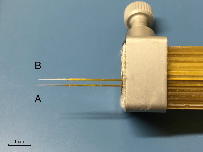
Figure 1: Set up of the Deep Brain Microwire Electrodes in a Standard Stereotaxic Holder. Note the tip separation between A, the electrode pair for the STN, and B, the electrode pair for the SNr in dorsoventral direction of approx. 200 µm and anterioposterior direction of approx. 2 mm. Please click here to view a larger version of this figure.

Figure 2
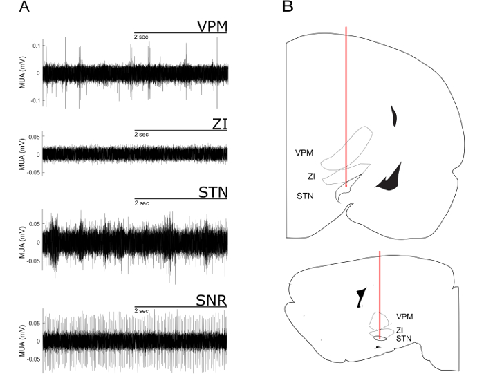
Figure 2: Characteristic Multi-unit Activity from a Dorsoventral Electrode Trajectory Targeting the STN. (A) Multi-unit recordings of the ventral posteromedial thalamic nucleus (VPM), the zona incerta (ZI), the subthalamic nucleus (STN) and the substantia nigra pars reticularis (SNr). The VPM exhibits sparse and irregular spaced high amplitude spikes. This pattern of spikes ceases when approaching the ZI. When the electrode enters the STN a typical high-frequency firing pattern with short bursts with medium amplitude can be observed. The SNr can be identified by its high amplitude and regular firing pattern. (B) STN-trajectories superimposed onto images from a rat stereotactic atlas21. Upper part: coronal plane. Lower part: sagittal plane. Note the passing of the electrode tip through VPM and ZI. Please click here to view a larger version of this figure.

Figure 3
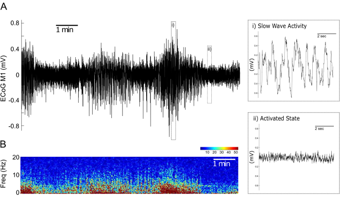
Figure 3. Cortical Synchronisation States in LFP Recordings from the Primary Motor Cortex during Urethane Anesthesia. (A) Representative 600 s LFP recording of the primary motor cortex. Time periods with high frequency, low amplitude activity corresponding to the Activated State (i) and time periods with a slower rhythm and higher amplitude corresponding to the Slow Wave Activity state (ii) can be differentiated. (B) Corresponding time-frequency plot over an interval of 600 s illustrating the 0-20 Hz relative power of the LFPs presented in (A). Warmer colorings indicate higher relative power. Please click here to view a larger version of this figure.

Figure 4
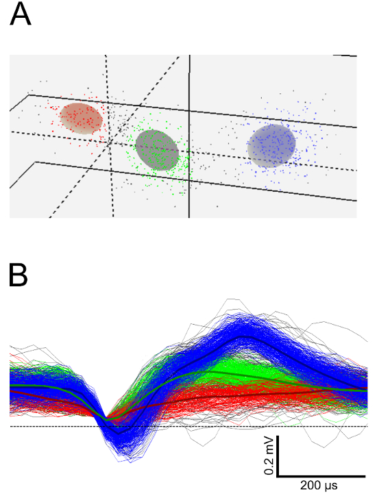
Figure 4: Sorting of Single Units from STN Multi-unit Activity. (A) Three-dimensional view of unit clusters in feature space after principal component analysis. Each cluster represents a putative single unit. (B) Spike waveforms and spike waveform averages corresponding to the clusters in (A). Please click here to view a larger version of this figure.

Coordinates from Bregma STN SNr M1 reference 1 reference 2
anterior-posterior -3.6 -4.8 +3.0 -10.0 -10.0
medial-lateral +2.5 +2.5 +3.0 +3.0 -3.0
dorsal-ventral -8.0 n. a.  n. a. n. a. n. a.

Table 1: Stereotaxic Coordinates for the Recording of the Hyperdirect Cortico-basal Ganglia Pathway. All points are measured from the bregma reference point on the skull in mm; n.a.- not applicable.

List of Materials

Ag/AgCl custom epidural electrodes Goodfellow GmbH
D-61213 Bad Nauheim, Germany
info@goodfellow.com
Product-ID AG005127 for 99.99% silver wire Ag/AgCl electrodes will allow for better signal quality, but may only be used in acute experiments. Possible replacement: Stainless steel electrodes
Stereotaxic holder with acrylic block David Kopf Instruments,
7324 Elmo Street, Tujunga, CA 91042, USA
Product ID Model 1770 Standard Electrode Holder Make sure the acrylic block has recesses which suit the electrode setup for the desired target. Acrylic blocks can easily be modified with a file to obtain the desired configuration. Possible replacement: Self-constructed electrode holders
Tungsten microwire electrodes 1.5 MΩ impedance Microprobes.com
18247-D Flower Hill Way  Gaithersburg, Maryland, 20879 USA
Product-ID WE3ST31.5A5-250um The 1.5 MΩ is necessary to record MUA and LFP at the same time. Possible replacement: Microelectrodes of different materials can be used. The electrodes have to be straight, robust and as thin as possible.
Rat alignment tool David Kopf Instruments,
7324 Elmo Street, Tujunga, CA 91042, USA
Product ID Model 944 Rat Alignment Tool Allows the exact orientation of the brain to match stereotaxic atlases. Possible replacement: Stereotaxic holder with a cannula
Two-component dental acrylic Associated Dental Products Ltd.
Kemdent Works, Purton, Swindon
Wiltshire, SN5 4HT, United Kingdom
Simplex Rapid Powder Clear 225g, Product code: ACR803; Simplex Rapid Liquid 150ml, Product code: ACR920 Depending in the electrodes used, superglue might be an easy alternative, if the electrodes are small and lightweight. Possible replacement: Superglue (Cyanacrylate-based)
Faraday cage Self-construction A proper Faraday cage will be the best protection from electromagnetic artifacts, but everything which can be formed into a box shape or applied to a frame and is made of conductive material may help. Possible replacement: Aluminum foil or copper mesh
Electrophysiological setup with recording software and online spike-sorting capabilities OmniPlex® Neural Data Acquisition System
Plexon Inc
6500 Greenville Avenue, Suite 700
Dallas, Texas 75206
USA
Offline sorting software is a potential alternative, multiple scripts and softwares can be found for free in the open source community.

Lab Prep

Converging evidence shows that many neuropsychiatric diseases should be understood as disorders of large-scale neuronal networks. To better understand the pathophysiological basis of these diseases, it is necessary to precisely characterize in which way the processing of information is disturbed between the different neuronal parts of the circuit. Using extracellular in vivo electrophysiological recordings, it is possible to accurately delineate neuronal activity within a neuronal network. The application of this method has several advantages over alternative techniques, e.g., functional magnetic resonance imaging and calcium imaging, as it allows a unique temporal and spatial resolution and does not rely on genetically engineered organisms. However, the use of extracellular in vivo recordings is limited since it is an invasive technique that cannot be universally applied. In this article, a simple and easy to use method is presented with which it is possible to simultaneously record extracellular potentials such as local field potentials and multiunit activity at multiple sites of a network. It is detailed how a precise targeting of subcortical nuclei can be achieved using a combination of stereotactic surgery and online analysis of multi-unit recordings. Thus, it is demonstrated, how a complete network such as the hyperdirect cortico-basal ganglia loop can be studied in anesthetized animals in vivo.

Converging evidence shows that many neuropsychiatric diseases should be understood as disorders of large-scale neuronal networks. To better understand the pathophysiological basis of these diseases, it is necessary to precisely characterize in which way the processing of information is disturbed between the different neuronal parts of the circuit. Using extracellular in vivo electrophysiological recordings, it is possible to accurately delineate neuronal activity within a neuronal network. The application of this method has several advantages over alternative techniques, e.g., functional magnetic resonance imaging and calcium imaging, as it allows a unique temporal and spatial resolution and does not rely on genetically engineered organisms. However, the use of extracellular in vivo recordings is limited since it is an invasive technique that cannot be universally applied. In this article, a simple and easy to use method is presented with which it is possible to simultaneously record extracellular potentials such as local field potentials and multiunit activity at multiple sites of a network. It is detailed how a precise targeting of subcortical nuclei can be achieved using a combination of stereotactic surgery and online analysis of multi-unit recordings. Thus, it is demonstrated, how a complete network such as the hyperdirect cortico-basal ganglia loop can be studied in anesthetized animals in vivo.

Procedure

Converging evidence shows that many neuropsychiatric diseases should be understood as disorders of large-scale neuronal networks. To better understand the pathophysiological basis of these diseases, it is necessary to precisely characterize in which way the processing of information is disturbed between the different neuronal parts of the circuit. Using extracellular in vivo electrophysiological recordings, it is possible to accurately delineate neuronal activity within a neuronal network. The application of this method has several advantages over alternative techniques, e.g., functional magnetic resonance imaging and calcium imaging, as it allows a unique temporal and spatial resolution and does not rely on genetically engineered organisms. However, the use of extracellular in vivo recordings is limited since it is an invasive technique that cannot be universally applied. In this article, a simple and easy to use method is presented with which it is possible to simultaneously record extracellular potentials such as local field potentials and multiunit activity at multiple sites of a network. It is detailed how a precise targeting of subcortical nuclei can be achieved using a combination of stereotactic surgery and online analysis of multi-unit recordings. Thus, it is demonstrated, how a complete network such as the hyperdirect cortico-basal ganglia loop can be studied in anesthetized animals in vivo.

Tags