The study was performed in accordance with the recommendations in the Guide for the Care and Use of Laboratory Animals of the National Institutes of Health. All animal procedures were approved by the Institutional Animal Care and Use Committee (IACUC) at the University of Kentucky (protocol 00903M2005).
1. Manufacturing and testing the nanopipettes
2. Minimizing sample drifts and vibrations
NOTE: To decrease the mechanical noise in the system during imaging, mount the samples on the custom-built chambers that utilize thick glass slides (~1.2 mm):
3.Testing the resolution with AFM calibration standards
NOTE: It is strongly recommended to image AFM standards (see Table of Materials) before imaging live cells in order to troubleshoot the system and test its resolution in the X-Z-Y axes. The calibration standards have silicon dioxide pillars and holes of different shapes but fixed heights/depths (i.e., 20 or 100 nm) on a 5 x 5 mm silicon chip. Starting with the 100 nm calibration standard is recommended, to guarantee that the Z resolution is below 100 nm. After achieving a successful high-resolution image of the pillars or holes in this calibration sample (Figure 3A), move to the 20 nm standard. If the imaging of the latter standard is successful (Figure 3B), the resolution in the Z axis is guaranteed to be below 20 nm and appropriate for the imaging of the hair cell stereocilia bundles12. The following steps are used to image both calibration standards.
4. Making custom-built chambers to secure the cochlear explants
NOTE: Mount the cochlear explants in the chambers with custom-built clamping systems that utilize either flexible glass pipettes (step 4.1) (Figure 4A) or dental floss (step 4.2) (Figure 4B). The glass pipette chamber could be sterilized and used for the cultured organs of Corti, while dental floss chamber provides a more secure holding of the sample and a control over stereocilia bundle orientation during mounting. These custom-built chambers need to be prepared in advance, but they can be cleaned and re-used in several imaging sessions.
5. Dissecting the rodent organ of Corti
6. Imaging of the auditory hair cells
7. Image processing
NOTE: Imaging artefacts are common in HPICM imaging. Some of them can be corrected by image acquisition parameters, while others require post-processing either with a specialized SICM viewer or with more general data-processing programs like ImageJ or MatLab. Here we describe the most common artefacts and how we fix them with SICM viewer.
The protocol presented in this paper can be used to visualize any live cells with complex topography. Following these steps, we routinely obtain images of live rat auditory hair cell bundles (Figure 6B,D). In spite of having lower X-Y resolution when compared to SEM images, our HPICM images can successfully resolve the different rows of stereocilia, the shape of the stereocilia tips, and even the small links (~5 nm in diameter) connecting adjacent stereocilia (Figure 6F). In addition, HPICM images have information in 3D that SEM images lack. Given the non-contact nature of this type of imaging technique, we were also able to perform continuous time-lapse HPICM imaging of the same hair cell bundle for several hours (i.e., 5-6 h regularly) without damaging the bundle cohesiveness (Figure 7). Thus, HPICM exhibits a great potential for the study of dynamic structural changes of the hair cell bundles over time.
Although we provide several ranges for pipette size, current setpoint, low- and high-resolution parameters, and hop amplitudes, each user might need to slightly optimize their settings to obtain successful HPICM images of live hair cell bundles. Smaller setpoints produce better quality images. However, with a very low setpoint, the system might interpret small fluctuations in the current as encountering the cell surface and this will lead to the "white dot" noise in the image (Figure 8A). Similarly, large hop amplitudes might increase the lateral resonance of the pipette and also produce noisy pixels (Figure 8B). In contrast, if the hop amplitude is too small or the setpoint is too high, the nanopipette might collide with the sample and lead to imaging artefacts or even damage the hair bundle (Figure 8C,D). We recommend performing the imaging at lower resolution while tweaking all these parameters to minimize damage to the sample or to the nanopipette.
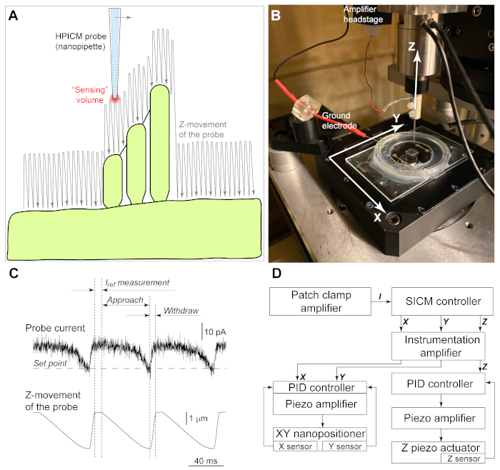
Figure 1: Principles of hopping probe ion conductance microscopy (HPICM). (A) An electric current passing through the nanopipette generates a "sensing volume" at the tip of the pipette. To image complex structures like the hair cell stereocilia bundles, the pipette approaches toward the cell surface from above and retracts after detecting the surface. After a lateral move at each step, the pipette continues to "hop" above the sample generating the image of the cell. Notice that the hop amplitude must be sufficient for the pipette to "climb" to a stereocilium. Illustrated hop amplitude would work for left-to-right scanning (from smallest to a tallest stereocilium, indicated by an arrow). However, it is too small for right-to-left scanning when the pipette meets the tallest stereocilium first. (B) Experimental setup. A custom-made chamber with the organ of Corti explant is mounted on a XY nanopositioning stage with an aperture for optical microscopy observation. The nanopipette is moved by a separate ultra-fast Z piezo actuator. To position the nanopipette over the region of interest, Z actuator is mounted on a conventional micromanipulator (not shown) together with the patch clamp amplifier headstage. Ground electrode is mounted on a magnetic holder and inserted into the bath. (C) Representative recordings of the pipette current (top trace) and Z position of the pipette (bottom trace) during imaging. When the pipette is away from the cell surface, the reference value of the current passing through the pipette is determined (Iref). Then, the pipette is moved toward the sample (approach). When the "sensing volume" meets the cell surface, the pipette current starts decreasing. The command for withdrawal is issued when the current decrease reaches a setpoint, which is typically 0.2% – 1% of Iref. (D) Schematics of the equipment that need to be added to a conventional patch clamp setup for HPICM imaging. A dedicated patch clamp amplifier records the nanopipette current (I) that is used by SICM controller in HPICM mode to generate command signals to X, Y, and Z axes. Instrumentation amplifier provides offset, scaling, and low pass filtering to these signals, if needed. Unfortunately, X/Y/Z signals from the controller cannot be applied directly to the piezo actuators due to large errors caused by hysteresis and creeping that are inherent to piezo ceramic. Therefore, each piezo actuator (translation stage) has a built-in motion sensor that sends feedback signal to the proportional-integral-derivative (PID) controller that pre-shapes the command signal to correct for these errors. Note that relatively slow X and Y axes could use PID controllers that are built in the piezo amplifier, while a faster Z axis requires a dedicated fast PID controller. Please click here to view a larger version of this figure.
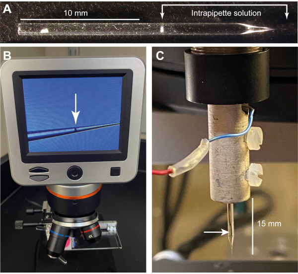
Figure 2: Nanopipette fabrication and filling. (A) An approximately 2 cm-long nanopipette filled with the intrapipette solution (HBSS). (B) An image of the bubble (arrow) that is typically formed after filling the pipette. The bubble usually moves away within few minutes of microscope illumination (an LCD digital microscope at 10x). (C) A nanopipette mounted into the SICM head. The arrow points to the AgCl electrode inside the pipette. Notice that the pipette holder is silver painted and grounded to minimize radiative electrical pickup from the Z piezo actuator. Please click here to view a larger version of this figure.
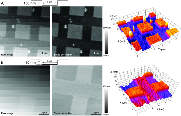
Figure 3: Imaging of AFM calibration standards to determine adequate stability, vibration isolation, and electrical noise in the system. (A) Raw (left), post-processed (middle), and 3D (right) images of the HS-100MG calibration standard. The surface profile of the standard is shown schematically at the top. Since the standard is never aligned perfectly perpendicular to the nanopipette, the post-processing slope correction is needed to reveal small vertical features of the sample. (B) Similar raw (left), post-processed (middle), and 3D (right) images of the HS-20MG calibration standard that has smaller, 20-nm deep indentations. Note that greyscale of a pixel in an HPICM image indicates the height of the sample at that point. Please click here to view a larger version of this figure.
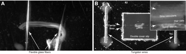
Figure 4: Mounting of the organ of Corti explant. (A) The explant is held by two glass pipettes that are glued to the glass-bottom Petri dish. (B) The explant is secured by two dental floss strands (short arrows) in a custom-made imaging chamber. Inset shows magnified image of the organ of Corti. Please click here to view a larger version of this figure.
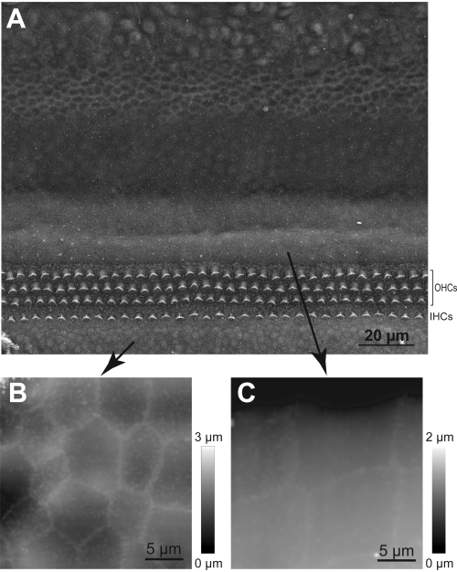
Figure 5: Navigation of the HPICM probe to the hair cell region. (A) SEM image of the cochlear explant showing rows of inner (IHCs) and outer (OHCs) hair cells and distinct types of supporting cells. (B) Representative HPICM image of the cells in Kolliker's organ. (C) An HPICM image of the Hensen's cells. Note that these two types of supporting cells have very distinct shapes, which helps determining whether the HPICM probe landed to an area that is radial or peripheral to the hair cells. Please click here to view a larger version of this figure.
Figure 6: Comparison between scanning electron microscopy (SEM) and hopping probe ion conductance microscopy (HPICM) imaging of stereocilia bundles in young postnatal rodent inner hair cells. (A,C) SEM images provide sub-nanometer resolution of the surface details but in the cells that are fixed and shrunk due to critical point drying. In addition, SEM images do not allow 3D analysis. (B,D) HPICM images (left) have a worse resolution (~5-10 nm) but they are obtained in live cells, allow time lapse imaging, and carry information on exact heights, which allows 3D reconstruction and measurements (right). (E,F) Extracellular links between stereocilia are evident in both SEM (E) and HPICM (F) images (arrows). Cell ages: A, postnatal day 5 (P5) mouse; B, P6 rat; C, P8 mouse; D, P5 rat; E, P7 mouse; and F, P5 rat. In all HPICM images, greyscale of a pixel indicates the height of the sample at that point. Please click here to view a larger version of this figure.
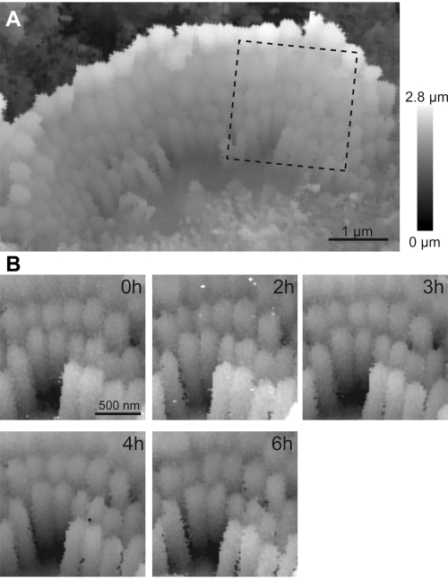
Figure 7: Continuous time lapse HPICM imaging of stereocilia bundle. (A) An overview of an inner hair cell bundle from P5 rat showing distinct shorter row stereocilia. (B) Time lapse imaging of the region of interest indicated in (A) throughout six hours. Note that, in contrast to a typical patch camp experiment, the hair cells show no signs of deterioration for several hours in vitro. This is due to careful dissection and the absence of any mechanical disturbances to the cell. Please click here to view a larger version of this figure.
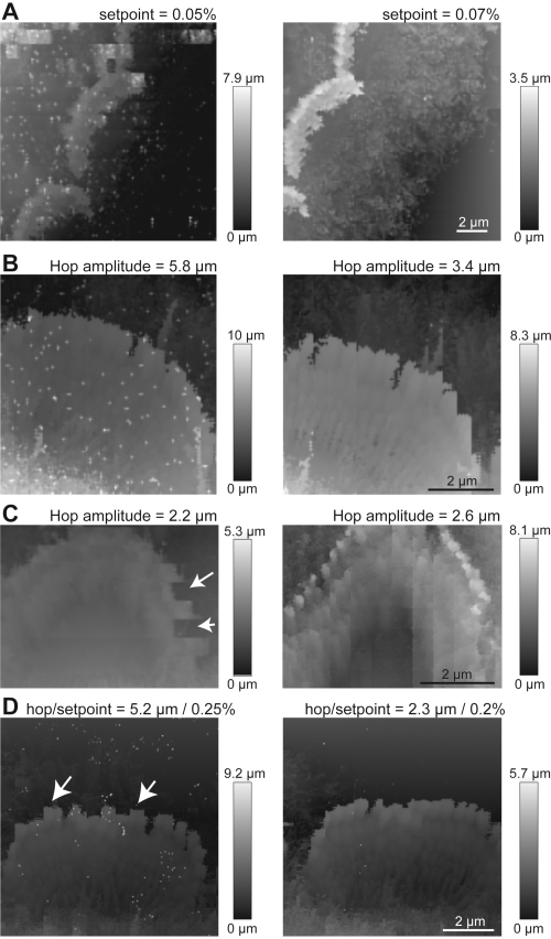
Figure 8: Common artefacts while imaging with HPICM. (A) Effect of a too low setpoint. Low-resolution HPICM images of the same live inner hair cell bundles in P3 mice acquired with setpoint 0.05% (left) and 0.07% (right). Notice a white dot noise that disappears with higher setpoint. (B) Effect of a too high hop amplitude. White dot noise also appears in an HPICM image of a P7 rat inner hair cell bundle obtained with a large hop amplitude of 5.8 µm (left). This noise disappears when the same bundle is imaged with the hop amplitude of 3.4 µm (right) due to the decrease of vibrations in the system. (C) Too low hop amplitude results in colliding of the HPICM probe to the stereocilia and dragging them (arrows on the left panel). Increasing the hop amplitude just enough to “climb over” stereocilia eliminates this artefact (right) but may also increase imaging time, resulting in a noticeable drift (vertical lines in the right panel). Stereocilia bundle of a live outer hair cell from P7 rat. (D) Too high setpoint causes a squared shape of stereocilia tips (arrows) in an HPICM image (left), again due to colliding of the nanopipette to the stereocilia. Decreasing setpoint (with simultaneous decrease of the hope amplitude to eliminate white noise) improves the imaging (right). Stereocilia bundle of a live inner hair cell from P6 rat. Please click here to view a larger version of this figure.
Resolution | Image area (µm) | Lateral Resolution (nm) | Time per image (minutes) |
Low | 20×20 | ≥300 | ≤20 |
Low | 10×10 | ≥156 | ≤15 |
Low | 5×5 | ≥75 | ≤4 |
High | 20×20 | ≤200 | ≤20 |
High | 10×10 | ≤110 | ≤15 |
High | 5×5 | ≤55 | ≤4 |
Table 1: Typical times of HPICM imaging depending on the size of imaging area and the scanning resolution.
Analog oscilloscope | B&K Precision | 2160C | Analog oscilloscope for real-time monitoring of nanopipette current and Z-axis approach |
AFM calibration standards | TED PELLA Inc | HS-100MG; HS-20MG | These 100 and 20 nm calibration standards are used to test the performance of HPICM system |
Benchtop vibration Isolator | AMETEK/TMC | Everstill K-400 | Active vibration isolation |
Borosilicate glass capillaries | World Precision Instruments (WPI) | 1B100F-4 | Borosilicate glass capillaries for the nanopipettes |
D-(+)-Glucose | Sigma-Aldrich | G8270 | To be added to the bath solution to adjust osmolarity |
Digitizer | National Instruments Corporation | PCI-6221 | Multi-channel input/output digitizer |
Fast analog Proportional-Integral-Derivative (PID) control for Z movement | Standford Research Systems | SIM900, SIM960, SIM980 | Instrumentation modules integrated in an external PID controller for Z movement. It requires a fast response that is usually not implemented in commercial piezo amplifiers. |
Faraday cage | AMETEK/TMC | Type II | Required to shield electromagnetic interference |
Glass bottom dish | World Precision Instruments (WPI) | FD5040-100 | Used as the dish for the chamber for the tissue |
Hanks' Balanced Salt Solution (HBSS) | Gibco, Thermo Fisher Scientific | 14025092 | Extracellular (bath) solution |
Instrumentation amplifier | Brownlee Precision | Model 440 | Instrumentation amplifier provides required offsets, filtering, and secondary magnification or attenuation |
Laser-based micropipette puller | Sutter Instrument | P-2000/G | Micropipette puller to fabricate the nanopipettes. Laser is needed for sharp quartz pipettes. |
Lebovitz's L-15, without phenol red | Gibco, Thermo Fisher Scientific | 21083027 | Extracellular (bath) solution |
Micromanipulator | Scientifica | PatchStar | Used for "course" positioning of the Z piezo actuator |
Microscope | Nikon | Eclipse TS100 | Inverted optical microscope |
Patch amplifier | Molecular Devices | Axopatch 200B | The patch clamp amplifier measures the current through the nanopipette |
Piezo amplifier (XY axes) | Physik Instrumente (PI) | E-500.00, E-505.00, E-509.C2A | Amplification and PID control for XY piezo translation stage |
Piezo amplifier (Z axis) | Piezosystem jena | ENT 400 & 800 | Custom amplifier consisting of ENT 400 power supply and two ENT 800 amplifiers in parallel to achieve max current of 1.6 nA |
Plastic Coverslips | TED PELLA Inc | 26028 | Used in the fabrication of the chambers for the tissue |
SICM controller & software* | Ionscope, UK (ionscope.com) | N/A | Custom controller based on SBC6711 digital signal processing board from Innovative Integration Ltd |
Silicone elastomer (Sylgard) | World Precision Instruments (WPI) | SYLG184 | Used to attach the flexible glass fibers to the chamber for the tissue |
Silicon glue | The Dow Chemical Company | 734 | Used to glue the different parts of the chamber for the tissue |
Tungsten rod | A-M Systems | 717500 | Used for holding the dental floss strands in the chamber for the tissue |
XY piezo nanopositioner | Physik Instrumente (PI) | P-733.2DD | XY translation stage with capacitive sensors |
Z piezo nanopositioner | Piezosystem jena | RA 12/24 SG | Ring piezoactuator with a strain gage sensor |
*Ionscope does not sell separate SICM controllers anymore. There are few other commercial systems: NX12-Bio and NX10 SICM, | |||
Park Systems, Korea and SICM modules from ICAPPIC Limited, UK (icappic.com). All these systems are based on the original | |||
HPICM principles. However, imaging stereocilia bundles in the hair cells requires several custom modifications that are technically | |||
challenging (or even impossible) in the closed “ready-to-go” systems such as Ionscope or NX12-Bio/NX10. Currently, there is only one | |||
modular system (ICAPPIC) that has the flexibility to suit any SICM/HPICM experiment but requires some component integration. |
Inner ear hair cells detect sound-induced displacements and transduce these stimuli into electrical signals in a hair bundle that consists of stereocilia that are arranged in rows of increasing height. When stereocilia are deflected, they tug on tiny (~5 nm in diameter) extracellular tip links interconnecting stereocilia, which convey forces to the mechanosensitive transduction channels. Although mechanotransduction has been studied in live hair cells for decades, the functionally important ultrastructural details of the mechanotransduction machinery at the tips of stereocilia (such as tip link dynamics or transduction-dependent stereocilia remodeling) can still be studied only in dead cells with electron microscopy. Theoretically, scanning probe techniques, such as atomic force microscopy, have enough resolution to visualize the surface of stereocilia. However, independent of imaging mode, even the slightest contact of the atomic force microscopy probe with the stereocilia bundle usually damages the bundle. Here we present a detailed protocol for the hopping probe ion conductance microscopy (HPICM) imaging of live rodent auditory hair cells. This non-contact scanning probe technique allows time lapse imaging of the surface of live cells with a complex topography, like hair cells, with single nanometers resolution and without making physical contact with the sample. The HPICM uses an electrical current passing through the glass nanopipette to detect the cell surface in close vicinity to the pipette, while a 3D-positioning piezoelectric system scans the surface and generates its image. With HPICM, we were able to image stereocilia bundles and the links interconnecting stereocilia in live auditory hair cells for several hours without noticeable damage. We anticipate that the use of HPICM will allow direct exploration of ultrastructural changes in the stereocilia of live hair cells for better understanding of their function.