1. Preparation of the PDMS piece
2. Experimental preparation for measuring micro-displacement
3. Image processing
4. Displacement calibration
5. Measuring micro displacement
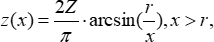
Following the protocol, the sensitivity of the micro-displacement measurement system can be calibrated, and the micro displacement can be measured. The shadow method in the micro-displacement measurement is presented as follows. Figure 3 shows the travel path of parallel light through the PDMS deformed surface due to the applied displacement. The refraction of parallel light forms a shadow having a bright edge. The explicit solution of displacements z(x) of the PDMS surface based on the Johnson-Kendall-Roberts (JKR) model is18:
(Equation 1)
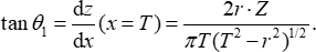
where Z is the applied displacement, and r is the radius of the rigid cylindrical leg. The incident angle θ1 of the outermost light can be expressed as Equation 2:
(Equation 2)
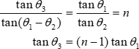
where T is the radius of the parallel light beam. The refraction angle θ3 of outgoing rays can be expressed as Equation 3 based on Snell's Law2 because tan θ1 tends to be zero:
(Equation 3)
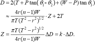
where n is the refractive index of PDMS. Finally, the relationship between the applied displacement and the shadow diameter change is12,17:
(Equation 4)
where P is the thickness of the PDMS piece, W is the working distance between the PDMS surface and the camera, and k is the sensitivity to be calibrated. According to Equation 4, the applied displacement is proportional to the shadow diameter change. Hence, the displacement can be measured by the shadow diameter change after the calibration.
Figure 4 illustrates the diameter fitting process of the shadow images. The original image represented by Figure 4A was converted to the grayscale image and preprocessed by Gaussian filtering and image enhancement, where Figure 4B was obtained. Figure 4C illustrates the sub-pixel edge contour set, which was acquired by the Canny operator. Figure 4D is the least squares circle fit for the circular shadow. Finally, the shadow diameter could be obtained with sub-pixel accuracy.
Figure 5 shows typical shadow images in the process of calibration. The shadow diameter increases as the applied displacement increases. It is observed that the shadow diameter changes symmetrically as the applied displacement increases and decreases.
Figure 6 shows the curve fit of mean values of the changes in shadow diameters due to micro-displacements. The slope of the fitted curve, which denotes the displacement sensitivity, was 10.0 nm/pixel with the fit goodness of 0.9995. Hence, according to Equation 4, the resolution of the measurement system was 10.0 nm when the circle fitting accuracy was 1 pixel. In the measurement range of 5 µm, the maximum deviation was 100.6 nm with a linearity error of 2.01%, which is shown in Figure 7.
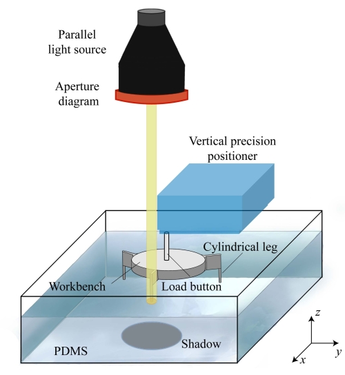
Figure 1: Schematic representation of the micro-displacement measurement system. Please click here to view a larger version of this figure.
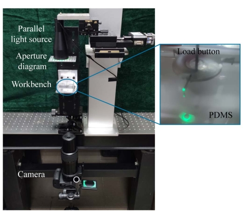
Figure 2: Appearance of the micro-displacement measurement system. Inset: Photo of a shadow for display. Please click here to view a larger version of this figure.
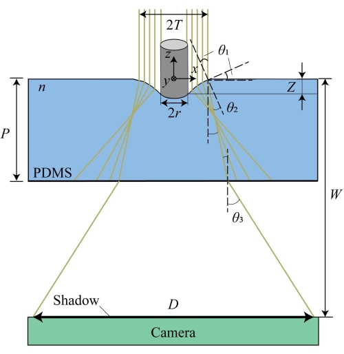
Figure 3: Travel path of parallel light beam through the bent surface of the PDMS. Z is the applied displacement. r is the radius of the rigid cylindrical leg. T is the radius of the parallel light beam. n is the refractive index of PDMS. P is the thickness of the PDMS piece. W is the working distance between the PDMS surface and the camera. θ1 and θ2 are the incident angle and the refraction angle of the outermost light. θ3 is the refraction angle of the outgoing rays. D is the shadow diameter. Please click here to view a larger version of this figure.
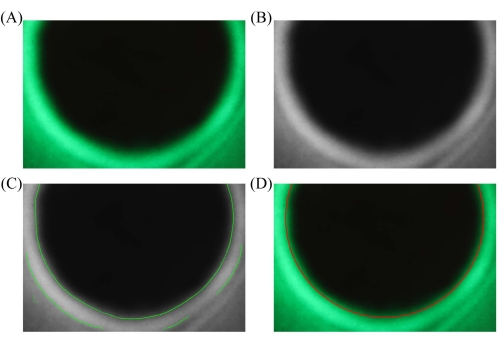
Figure 4: Typical processing of the shadow image. (A) RGB shadow image. (B) Preprocessing image. (C) Sub-pixel edge. (D) Least-squares circle fitting. Please click here to view a larger version of this figure.
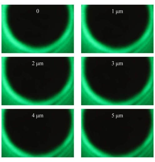
Figure 5: Typical shadow images in the process of calibration. The applied displacements are 0 µm, 1 µm, 2 µm, 3 µm, 4 µm, and 5 µm, respectively. Please click here to view a larger version of this figure.
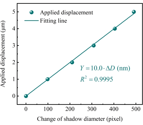
Figure 6: Results of micro-displacement. The displacement sensitivity was 10.0 nm/pixel. The goodness of the linear fitting was 0.9995, determined by the least squares method. Please click here to view a larger version of this figure.
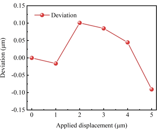
Figure 7: Error distribution curve of the displacement calibration. Please click here to view a larger version of this figure.
Aperture diaphragm | Processed by high precision grinding | The diameter of the aperture is 0.7 mm. | |
Camera | Canon | EOS80D | The pixel size and the resolution of the camera are about 3.72 μm and 4000 × 6000, respectively. |
HALCON | MVTec Software GmbH | 18.11 | MVTec HALCON is the comprehensive standard software for machine vision with an integrated development environment (HDevelop) that is used worldwide. |
Motorized linear stage | Zolix | TSA50-C | Resolution 0.625 μm |
Parallel light source | Oriental Technology (Shanghai) Co, Ltd. | BTPL-50G | The peak wavelength is 523 nm. |
Polydimethylsiloxane (PDMS) | Dow Corning | Sylgard 184 | PDMS is a transparent silicon-based crosslinked polymer. |
Vacuum pump | SHANGHAI LICHEN-BX INSTRUMENT TECHONOLOGY CO.,Ltd | 2XZ-6B | The pumping rate is 6 L/s.The ultimate vacuum is ≤1 Pa |
Vertical precision positioner | PI | P-620.ZCD | The resolution is 0.2 nm in the range of 50 μm. |
Workbench with three rigid cylindrical legs | Processed by high precision grinding | The diameter of legs is 0.5 mm. The legs are distributed on the trisection points of a circle with a radius of 14 mm |
The precision measurement of micro displacement is important in scientific and industrial fields. However, it is a tough challenge due to the complex design and the high cost of measuring instruments. Inspired by the shadow formed from water striders walking on a water surface under sunlight, a micro-displacement measurement method was proposed. Water strider legs with superhydrophobic properties bend the water surface. The curved surface of the water refracts sunlight, creating a shadow with a bright edge at the bottom of the pond. The shadow size is generally larger than the indentation depth of the legs from the water surface. In the micro-displacement measurement system, the applied displacement is proportional to the change in the diameter of the shadow. The presented study proposes a micro-displacement measurement procedure based on this shadow technique. The displacement sensitivity can reach 10.0 nm/pixel in the range of 5 µm. This system is simple to construct, low cost, and has high precision with good linear performance. The method provides a convenient additional option to measure micro-displacement.