JoVE 科学教育
Chemical Engineering
需要订阅 JoVE 才能查看此.  登录或开始免费试用。
JoVE 科学教育 Chemical Engineering
Testing the Heat Transfer Efficiency of a Finned-tube Heat Exchanger
  • 00:07概述
  • 00:59Principles of Heat Transfer in Heat Exchangers
  • 04:07Heat Exchanger Start-up
  • 04:54Flow Rate Variation
  • 05:42Calculations
  • 06:09Results
  • 07:26Applications
  • 08:11Summary

Prueba de la eficiencia de transferencia de calor de un intercambiador de calor de tubos con aletas

English

分享

概述

Fuente: Michael G. Benton y Kerry M. Dooley, Departamento de Ingeniería Química, Universidad Estatal de Luisiana, Baton Rouge, LA

Los intercambiadores de calor transfieren calor de un fluido a otro. Existen varias clases de intercambiadores de calor para satisfacer diferentes necesidades. Algunos de los tipos más comunes son intercambiadores de carcasas y tubos e intercambiadores de placas1. Los intercambiadores de calor de carcasa y tubo utilizan un sistema de tubos a través del cual fluye el fluido1. Un conjunto de tubos contiene el líquido que se va a enfriar o calentar, mientras que el segundo conjunto contiene el líquido que absorberá el calor o lo transmitirá1. Los intercambiadores de calor de placas utilizan un concepto similar, en el que las placas se unen estrechamente junto con un pequeño espacio entre cada uno para que el líquido fluya1. El fluido que fluye entre las placas alterna entre caliente y frío para que el calor entre o salga de las corrientes necesarias1. Estos intercambiadores tienen grandes superficies, por lo que suelen ser más eficientes1.

El objetivo de este experimento es probar la eficiencia de transferencia de calor de un intercambiador de calor de tubo aleteado (Figura 1) y compararlo con la eficiencia teórica de un intercambiador de calor sin aletas. Los datos experimentales se medirán para tres caudales diferentes de monoetilenglicol (MEG). Se utilizarán dos caudales de agua diferentes para cada caudal MEG. Utilizando el método de trazado Wilson, los coeficientes de transferencia de calor se determinarán a partir de los datos experimentales. Además, el número del Reynold y la cantidad de calor transferido se compararán para el flujo con y sin las aletas para evaluar la eficiencia de transferencia de calor.

Figure 1
Figura 1: Intercambiador de calor de tubo finlandés. 1) Temperatura de salida MEG 2) temperatura de entrada de agua 3) temperatura de entrada MEG 4) temperatura de salida de agua 5) medidor de agua 6) MEG acumulación de vidrio/ cilindro.

Principles

Procedure

1. Determinación de la velocidad de inicio y flujo Abra la válvula de carga situada debajo del generador de vapor. Encienda la unidad y espere 15 minutos para que el vapor comience a formarse. Calcular el caudal de agua Inicie un cronómetro y monitoree el medidor que muestra el volumen de agua. Detenga el reloj después de 30 s y registre el volumen total de agua que se muestra en el medidor. Divida el volumen de agua por el tiempo para determinar el caudal v…

Results

The finned tube heat exchanger did not reach turbulent flow (Figure 2). The fins provide additional surfaces on which boundary layers form, as known through laminar and turbulent flow theory. If the fluid is not at a sufficient velocity, the fluid will not reach turbulence. The boundary layers between the fins overlap in the laminar region, so the fluid will remain laminar.

Figure 2
Figure 2: Reynolds numbers for each setting.

The amount of heat transferred, Q, in the tubes with and without fins at different flow rates of MEG was compared (Figure 3). The results show that a finned-tube transfers more heat than a tube without fins at the same operating conditions. In this experiment, the fins clearly improved heat transfer. This is because heat transfer is more effective when there is a greater surface area available. The finned-tube heat exchanger transferred more heat (Figure 3), despite the lower Reynolds number (Figure 2).

Figure 3
Figure 3: Heat transferred between exchangers with and without fins at each flow rate.

Applications and Summary

Heat exchangers are used in a variety of industries, including agriculture, chemical production, and HVAC. The goal for this experiment was to test the heat transfer efficiency of a finned-tube heat exchanger and compare it to the theoretical efficiency of a heat exchanger without fins. Experimental data was measured for three different flow rates of monoethylene glycol (MEG) and two unique water flow rates for each MEG flow rate used. The Reynold’s number was determined for flow with and without the fins and was used to calculate the heat transfer coefficient, surface area, and fin efficiency for each unique trial run. This data was used to evaluate if turbulent flow is possible without the fins and under which set of trial conditions the most heat transfer occurs. The finned tubes did not reach turbulent flow. The results showed that a fin tube will transfer more heat than a tube without fins at the same operating conditions because the flow of MEG through the heat exchanger will not reach turbulence.

In the agriculture industry, heat exchangers are used in the processing of sugar and ethanol2. Both of these products are processed into a juice, which must be heated to be further processed2. Heat exchangers are used in heating the juices for clarification2. Once the juices have been processed into even syrups, further heating with exchangers is necessary to continue processing and form molasses2. Molasses is cooled using heat exchangers, after which it can be stored for later processing2.

Heating, ventilation, and air conditioning systems, together known as HVAC, all make use of heat exchangers3. Household air conditioning and heating units make use of heat exchangers3. In larger settings, chemical plants, hospitals, and transportation centers all make use of similar heat exchanger HVAC, on a much larger scale3. In the chemical industry, heat exchangers are used for heating and cooling a large variety of processes4. Fermentation, distillation, and fragmentation all make use of heat exchangers4. Even more processes like rectification and purification require heat exchangers4.

References

  1. Types of Heat Exchangers." Types of Heat Exchangers. N.p., n.d. Web. 19 Jan. 2017.
  2. Heat exchangers for sugar factories and distilleries." Heat exchanger for sugar and ethanol industry. N.p., n.d. Web. 19 Jan. 2017.
  3. Biotechnology and green chemistry heat exchangers." Heat exchanger for green chemical industry. N.p., n.d. Web. 19 Jan. 2017.
  4. Heat exchangers for heating and cooling." Heat exchangers for district heating, cooling and HVAC. N.p., n.d. Web. 19 Jan. 2017.

成績單

Heat exchangers transfer heat between two species and are used for a wide variety of applications from car radiators to large-scale chemical plants. There are many heat exchanger designs including shell and tube exchangers and finned tube exchangers. For these an array of tubes and fins is used to transfer heat from the hot fluid to the cold fluid. An understanding of the heat transfer efficiency is important for heat exchanger design optimization and their integration into larger systems. This video will illustrate the principles of heat exchangers, demonstrate how to calculate the heat transfer coefficient and efficiency for a finned tube heat exchanger and discuss related applications.

Now, let’s look at how heat exchangers work and examine the principles governing their efficiency. The heat transfer in a heat exchanger is generated by fluid species in close contact that are separated by a physical barrier. They can flow either parallel or counter currently to each other. Heat exchange is driven by local temperature differences between the fluids. The hotter of the two fluids entering the heat exchanger will exit with a reduced temperature whereas the colder will exit with an increased temperature. The heat transfer efficiency can be increased by the addition of fins to the flow area which increases the surface area available for heat transference. However, the added fins also decrease the region through which the fluid flows, providing more surfaces for boundary layers to form. A boundary layer is the thin layer of fluid in contact with the surface that is affected by shearing forces. When the boundary layer is laminar, there is very little mixing and heat transfer is inhibited. At higher flow rates, or longer distances, the laminar flow breaks down and transitions to a turbulent flow where the bulk fluid mixes more effectively. During steady state operation, the total heat transferred, Q, can be calculated using the overall heat transfer coefficient U, the area through which the heat flows, A and delta TLM, the logarithmic mean temperature difference between the bulk fluid flow and the heat surface. UA is the overall conductance and is a measure of the heat transfer capacity of a heat exchanger. The overall heat transfer coefficient is determined by this equation which takes into account the surface areas of the pipe and fins, the heat transfer coefficients and the thermal conductivity and thickness of the pipe. The heat transfer coefficient is estimated from experimental data using graphical methods such as the Wilson plot which plots the reciprocal of the overall conductance versus one over the Reynolds raised to the eight tenths power. Linear regression is used to solve for the heat transfer coefficients. The dimensionless Reynold’s number is the ration of inertial forces to viscous forces and it used to describe flow pattern. Where D is the equivalent diameter of the pipe, G is the mass velocity of the fluid and Mu is the viscosity of the fluid. A higher Reynold’s number indicates a more turbulent flow, greater fluid mixing and increased heat transfer. Now that you understand how to calculate the heat transfer coefficients and Reynold’s numbers, let’s evaluate the heat transfer efficiency of a finned tube heat exchanger by varying the flow rates of water and monoetilenglicol.

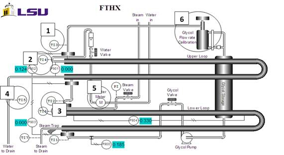
Before your start, familiarize yourself with the finned tube heat exchanger apparatus. Open the charge valve, start the unit and wait for steam to begin forming. Using a stopwatch and the gauge, determine the water flow rate. Start your stopwatch and monitor the gauge displaying the volume of water. Stop the stopwatch after 30 seconds. Record the total volume of water on the gauge and divide the volume by the measured time. Next, read the MEG flow rate on the display. When the 30 seconds for flow rate calculation have passed, record the temperature from the thermocouples.

Now, vary the flow rates to obtain data for six unique runs. Each run consists of a set water and MEG flow rate. Set the water flow rate to either high or low and run it with a high, medium or low flow rate of MEG for a total of six runs. Repeat the same procedure above for each flow rate to record the volumetric flow rates of water and MEG and the temperature difference from the thermocouple. When finished, shut down the instrument. Close the valves for the steam, glycol and water flow. Then turn off the main switch.

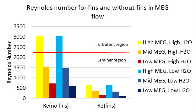
To calculate the total heat transferred, Q, for each run, use the obtained temperature differences from each experiment and the physical parameters of monoetilenglicol. Then determine the Reynold’s number for each unique run using the dimensions of the pipe and the mass velocity and viscosity of water.

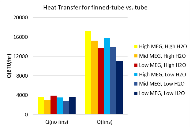
Now let’s compare the results to the theoretical values of the heat exchanger without fins. A Wilson plot was used to determine the heat transfer coefficients by plotting one over UA, versus one over the Reynold’s number raised to the eight tenths power and relating the linear fit to the equation for the overall heat transfer coefficient. The blue, red and green lines indicate the high, middle and low monoetilenglicol flow rates in the experiment. When compared to a non-finned tube, the finned tube did not reach turbulent flow. The fins provide additional surfaces for boundary layers to form and maintain the monoethylene glycol in a more laminar flow regime. However, when comparing the heat transferred between the exchanger with and without fins at different MEG flow rates, it is clear that a finned tube transferred more heat than a tube without fins at the same operating settings. Heat transfer is more effective with a greater surface area, despite the fact that the finned tubes induce laminar flow, their heat efficiency was much higher than for the non-finned tube.

Heat exchangers are used in a variety of settings to transfer heat from one species to another. In all buildings, heat exchangers are part of the heating and air conditioning systems to regulate temperature. They are also used to control core patient temperature in critical care settings, such as after cardiac arrest, neurogenic fever or surgery. Heat exchangers are also used on the small scale in the denature and heat precipitation of proteins from plant extracts. This technique was used in the extraction of a malarial vaccine candidate from transgenic tobacco plants to reduce the concentration of host cell proteins.

You’ve just watched JoVE’s introduction to finned tube heat exchangers. You should now understand the principles of heat transfer, be able to evaluate heat efficiency and know several applications of heat exchangers in various processes. Thanks for watching.

Tags

Cite This
JoVE Science Education Database. JoVE Science Education. Testing the Heat Transfer Efficiency of a Finned-tube Heat Exchanger. JoVE, Cambridge, MA, (2023).