Summary

Convergent Polishing: A Simple, Rapid, Full Aperture Polishing Process of High Quality Optical Flats & Spheres

Published: December 01, 2014
doi:

Summary

A novel optical polishing process, called “Convergent Polishing”, which enables faster, lower cost polishing, is described. Unlike conventional polishing processes, Convergent Polishing allows a glass workpiece to be polished in a single iteration and with high surface quality to its final surface figure without requiring changes to polishing parameters.

Abstract

Convergent Polishing is a novel polishing system and method for finishing flat and spherical glass optics in which a workpiece, independent of its initial shape (i.e., surface figure), will converge to final surface figure with excellent surface quality under a fixed, unchanging set of polishing parameters in a single polishing iteration. In contrast, conventional full aperture polishing methods require multiple, often long, iterative cycles involving polishing, metrology and process changes to achieve the desired surface figure. The Convergent Polishing process is based on the concept of workpiece-lap height mismatch resulting in pressure differential that decreases with removal and results in the workpiece converging to the shape of the lap. The successful implementation of the Convergent Polishing process is a result of the combination of a number of technologies to remove all sources of non-uniform spatial material removal (except for workpiece-lap mismatch) for surface figure convergence and to reduce the number of rogue particles in the system for low scratch densities and low roughness. The Convergent Polishing process has been demonstrated for the fabrication of both flats and spheres of various shapes, sizes, and aspect ratios on various glass materials. The practical impact is that high quality optical components can be fabricated more rapidly, more repeatedly, with less metrology, and with less labor, resulting in lower unit costs. In this study, the Convergent Polishing protocol is specifically described for fabricating 26.5 cm square fused silica flats from a fine ground surface to a polished ~λ/2 surface figure after polishing 4 hr per surface on a 81 cm diameter polisher.

Introduction

The major steps in a typical optical fabrication process include shaping, grinding, full aperture polishing, and sometimes small tool polishing1-3. With increasing demand for high quality optical components for imaging and laser systems, there have been significant advancements in optical fabrication over the last several decades. For example, precision, deterministic material removal is now possible during the shaping and grinding processes with advancements in Computer Numerical Controlled (CNC) glass shaping machines. Similarly, small tool polishing technologies (e.g., computer controlled optical surfacing (CCOS), ion figuring, and magneto-rheological finishing (MRF)) have led to deterministic material removal and surface figure control, thus strongly impacting the optical fabrication industry. However, the intermediate step of the finishing process, full aperture polishing, still lacks high determinism, typically requiring skilled opticians to carry out multiple, often long, iterative cycles with multiple process changes to achieve to the desired surface figure1-3.

The large number of polishing methods, process variables, and the complex chemical and mechanical interactions between the workpiece, lap and slurry3-4 have made it challenging to transform optical polishing from an ‘art’ to a science. To achieve deterministic full aperture polishing, the material removal rate must be well understood. Historically, material removal rate has been described by the widely used Preston equation5

Equation 1 (1)

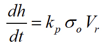
where dh/dt is the average thickness removal rate, kp is the Preston constant, σo is the applied pressure, and Vr is the average relative velocity between the workpiece and the lap. Figure 1 schematically depicts the physical concepts that influence material removal rate as described the Preston Equation, including spatial and temporal variations in velocity and pressure, differences between the applied pressure and the pressure distribution that the workpiece experiences, and friction effects6-8. In particular, the actual pressure distribution experienced by the workpiece is governed by a number of phenomena (described in detail elsewhere6-8) which strongly affect resulting surface figure of the workpiece. Also, in the Preston Equation, the microscopic and molecular level effects are largely folded into the macroscopic Preston constant (kp), which influences the overall material removal rate, micro-roughness, and even scratching on the workpiece. Various studies have expanded Preston’s model to account for microscopic slurry particle-pad-workpiece interactions to explain material removal rate and microroughness9-16.

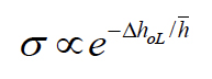
To achieve deterministic control of surface figure during full aperture polishing, each of the phenomena described above needs to be understood, quantified and then controlled. The strategy behind Convergent Polishing is to eliminate or minimize the undesirable causes of non-uniform material removal, either through engineered polisher design or by process control, such that removal is driven only by the workpiece-lap mismatch due to workpiece shape7,17-18. Figure 2 illustrates how workpiece shape can lead to convergence based on the workpiece-lap mismatch concept. Consider a flat lap and a hypothetical workpiece of complex shape shown at the top left. The interface height mismatch (referred to as the gap, ΔhoL) influences the interface pressure distribution (σ) as:

Equation 2 (2)

where h̅ is a constant describing the rate at which the pressure declines with an increase in gap ΔhoL6. In this example, the workpiece has the highest local pressure in the center (see bottom left of Figure 2), and hence this location will observe the highest initial material removal rate during polishing. As material is removed, the pressure differential across the workpiece will decrease due to a decrease in the workpiece-lap mismatch, and the workpiece will converge to the shape of the lap. At convergence, the workpiece pressure distribution, and hence material removal, will be uniform across the workpiece (see right side of Figure 2). This example is illustrated for a flat lap, however, the same concept applies for a spherical lap (either concave or convex). Again, this convergence process only works if all the other phenomena affecting spatial material non-uniformity have been eliminated. The specific procedural and engineering mitigations implemented in the Convergent Polishing protocol are described in the Discussion.

The protocol described in the following study is the Convergent Polishing process specifically for a 26.5 cm square fused silica glass workpiece starting from a fine ground surface. In 8 hours of polishing (4 hours/surface), this workpiece can achieve a polished flatness of ~λ/2 with very high surface quality (i.e., low scratch density).

Protocol

1. Preparation of Polisher and Slurry First prepare the Convergent Polishing System (specifically called Convergent, Initial Surface Independent, Single Iteration, Rogue Particle-Free Polisher or CISR (pronounced ‘scissor’))7,17 by installing the pad & septum, conditioning the pad, diluting & chemic…

Representative Results

The Convergent Polishing protocol described above allows a ground fused silica workpiece (in this case a 26.5 cm square) to be polished, in a single iteration of 4 hr per surface, to a peak-to-valley flatness of ~λ/2 (~330 nm) for low aspect ratio workpieces and ~1λ (~633 nm) for high aspect ratio workpieces (see Figure 3). Again, this process repeatedly converges workpieces to the same final surface figure without requiring changes to polishing parameters and is independent of the initial surf…

Discussion

As discussed in the Introduction, successful implementation of Convergent Polishing with respect to surface figure involves eliminating or minimizing all the phenomena that influence spatial material non-uniformity except that of workpiece-lap mismatch due to workpiece shape. If any one of these phenomena is not appropriately mitigated, either through process control or through appropriate engineering of the polisher, then the desired convergence point cannot be achieved or maintained; hence essentially every mitigation …

Disclosures

The authors have nothing to disclose.

Acknowledgements

This work performed under the auspices of the U.S. Department of Energy by Lawrence Livermore National Laboratory under Contract DE-AC52-07NA27344 within the LDRD program.

Materials

Name of Material/Equipment Company Catalog Number
MHN 50 mil Polyurethane Pad  Eminess Technologies PF-MHN15A050L-56
Cerium oxide polishing slurry Universal Photonics HASTILITE PO
Septum Glass (waterjet cut) Borofloat ; Schott  NA
Diamond conditioner Morgan Advanced Ceramics  CMP-25035-SFT
Ultrasonic Cleaner Advanced Sonics Processing System URC4
Purification Optima Filter cartridge 3M CMP560P10FC
Blocking Pitch Universal Photonics BP1
Blocking Tape 3M #4712
Cleanroom Cloth ITW Texwipe AlphaWipe TX1013
Single Particle Optical Sensing Paritcle Sizing Systems Accusizer 780 AD

References

  1. Anderson, D., Burge, J., Thompson, B., Malacara, D. Ch 28. Handbook of optical engineering. Optical fabrication. , (2001).
  2. Karow, H. . Fabrication Methods for Precision Optics. , (1993).
  3. Brown, N. J. A short course in optical fabrication technology. , (1981).
  4. Cook, L. Chemical processes in glass polishing. J. Non-Crystal. Solids. 120, 152-171 (1990).
  5. Preston, F. The Structure of Abraded Glass Surfaces. Trans. Opt. Soc. 23 (3), 141-14 (1922).
  6. Suratwala, T., Feit, M., Steele, R. Toward Deterministic Material Removal and Surface Figure During Fused Silica Pad Polishing. J. Am. Ceram. Soc. 93 (5), 1326-1340 (2010).
  7. Suratwala, T., Steele, R., Feit, M., Desjardin, R., Mason, D. Convergent Pad Polishing of amorphous fused silica. International Journal of Applied Glass Science. 3 (1), 14-28 (2012).
  8. Suratwala, T., Feit, M., Steele, R., Wong, L. Influence of Temperature and Material Deposit on Material Removal Uniformity during Optical Pad Polishing. J. Am. Ceram. Soc. , (2014).
  9. Suratwala, T. Microscopic removal function and the relationship between slurry particle size distribution and workpiece roughness during pad polishing. J. Am. Ceram. Soc. 91 (1), 81-91 (2014).
  10. Terrell, E., Higgs, C. Hydrodynamics of Slurry Flow in Chemical Mechanical Polishing. J. Electrochem. Soc. 153 (6), 15-22 (2006).
  11. Runnels, S., Eyman, L. Tribology Analysis of Chemical MechanicalPolishing. J. Electrochem. Soc. 141 (6), 1698-1701 (1994).
  12. Park, S., Cho, C., Ahn, Y. Hydrodynamic Analysis of Chemical Mechanical Polishing Process. J. Tribology Int. 33, 723-730 (2000).
  13. Luo, J., Dornfeld, D. Effects of Abrasive Size Distribution in Chemical Mechanical Planarization: Modeling and Verification. IEEE T. Semicond. M. 16 (3), 469-476 (2003).
  14. Luo, J., Dornfeld, D. Material Removal Mechanism in Chemical Mechanical Polishing: Theory and Modeling. IEEE T. Semiconduct. M. 14, 112-133 (2001).
  15. Bastaninejad, M., Ahmadi, G. Modeling the Effects of Abrasive Size Distribution, Adhesion, and Surface Plastic Deformation on Chemical Mechanical Polishing. J. Electrochem. Soc. 152 (9), 720-730 (2005).
  16. Sampurno, Y., Sudargho, F., Zhuang, Y., Ashizawa, T., Morishima, H., Philipossian, A. Effect of Cerium Oxide Particles Sizes in Oxide Chemical Mechanical Planarization. Electrochem. Solid State. 12 (6), 191-194 (2009).
  17. Suratwala, T., et al. Method and system for Convergent Polishing. US Provisional Patent Application. , (2011).
  18. Suratwala, T., Feit, M., Steele, R. Apparatus and Method for Deterministic Control of Surface Figure During Full Aperture Polishing. US Patent Application. US. , (2010).
  19. Dylla-Spears, R., Feit, M., Miller, P., Steele, R., Suratwala, T., Wong, L. Method for preventing agglomeration of charged colloids without loss of surface activity. US Provisional Patent Application. , (2012).
  20. Dylla-Spears, R., Wong, L., Miller, P., Feit, M., Steele, R., Suratwala, T. Charged Micelle Halo Mechanism for Agglomeration Reduction in Metal Oxide Particle Based Polishing Slurries. Colloid Surface A. 447, 32-43 (2014).
  21. Wong, L., Suratwala, T., Feit, M., Miller, P., Steele, R. The Effect of HF/NH4F Etching on the Morphology of Surface Fractures on Fused Silica. J. Non-Crystal. Solids. 355, 797 (2009).
  22. Feit, M., DesJardin, R., Steele, R., Suratwala, T. Optimized pitch button blocking for polishing high-aspect-ratio optics. Appl. Opt. 51 (35), 8350-8359 (2013).
  23. Suratwala, T., et al. Sub-surface mechanical damage distributions during grinding of fused silica. J. Non-Crystal. Solids. 352, 5601 (2006).
  24. Miller, P., et al. The Distribution of Sub-surface Damage in Fused Silica. SPIE. 5991, (2005).
  25. Suratwala, T., et al. Effect of Rogue particles on the sub-surface damage of fused silica during grinding/polishing. J. Non-Crystal. Solids. 354, 2003 (2008).
  26. Suratwala, T., Miller, P., Ehrmann, P., Steele, R. Polishing slurry induced surface haze on phosphate laser glasses. J. Non-Crystal. Solids. 351, 2091-2101 (2004).
check_url/cn/51965?article_type=t

Play Video

Cite This Article
Suratwala, T., Steele, R., Feit, M., Dylla-Spears, R., Desjardin, R., Mason, D., Wong, L., Geraghty, P., Miller, P., Shen, N. Convergent Polishing: A Simple, Rapid, Full Aperture Polishing Process of High Quality Optical Flats & Spheres. J. Vis. Exp. (94), e51965, doi:10.3791/51965 (2014).

View Video