Zone melting directional solidification is a metallurgical method employed to prepare stable phases in solid materials. During the solidification process, a melted alloy cools into various phases that form the solid. Using a directional solidification furnace, the process of phase formation and stabilization inside a solid material, is well controlled. This video will illustrate the principles of directional solidification and show how to apply them in the laboratory setting, to develop stable microstructures in a solid sample.
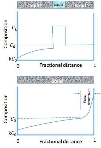
To begin, let us have a closer look at the process of solidification itself, which involves the cooling of a liquid. As the temperature decreases, particles of the liquid move slower and start to nucleate, to form what is called “the solid phase.” This principle is illustrated in a phase diagram that shows the different phases of the material as the temperature varies. In the vicinity of the solid-liquid interphase, the process of particle diffusion in the liquid occurs. This may cause mixing, and a convection current in the melt, leading to the formation of unstable microstructures. The alloy in this video is formed of two types of solid phases: an alpha phase, and a beta phase. In the particular case of a peritectic reaction, a solid phase alpha interacts with a liquid, to form a second solid-phase beta. At low growth rate, alternating bands of alpha and beta phases form.
This is called the “banding process.” The banding structure is the result of the oscillatory modes of convection inside the liquid. The composition range, the convection in the liquid, the nucleation temperature, and the growth velocity will dictate the characteristics of the banding results. These are defined by the width of the individual bands, the space between them, and their stability. Using a zone melting-freezing furnace in a vertical direction, is a neat way to control the solidification process. In this experiment, a solid is moved to the furnace where a liquid is prepared, then it is transferred immediately to a cooling zone that freezes the melted material. This transition can be performed rapidly enough to avoid the convection inside the liquid phase. The thermal gradient between the hot and cold zones and the velocity can be easily adjusted to control the growth conditions of the solid phases. We will now see how these principles apply in an experiment using a zone-melting directional solidification furnace.
First, take a 30cm long Pyrex tube, having an 8mm outside diameter. Choose a 100-micron Chromel Alumel thermocouple, covered in a 0.1cm double-bore mullite protection tube and having its tip coated with a boron-nitride slurry. Then carefully insert the thermocouple in the Pyrex tube. Next, weigh the alloy samples and place them in a crucible. Leave the crucible inside a furnace until the alloy is melted. Attache a bulb to the end of the Pyrex tube, then use the bulb to apply suction and draw the melt into the glass tube. The rode formed inside the tube will be used in our next experiment.
Place the sample inside the custom-built apparatus specifically designed and developed for vertical solidification. This setup consists of a furnace sandwiched between two cooling systems. The distance between the heating element and the following Cho Zone is set at 0.5cm. Connect the thermocouple to the data acquisition module and then connect this module to the computer. From the bottom to top, proceed to a vertical run of the furnace. Record the run time and determine the velocity of the furnace movement along the Pyrex tube. Determine the thermal gradient by taking the difference between the temperature of the melted alloy inside the furnace, and the temperature in the chill zone.
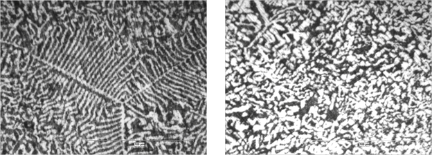
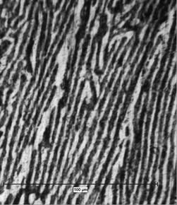
First, break the glass tube to remove this sample. Use the band saw to cut the sample into the desired length, and then mount the sample using epoxy resin. Proceed to polishing the sample in the following steps. First, use a silicon-carbide paper of grade 600, then polish with a silicon-carbide paper of grade 800, and finally of grade 1200. Now use Alumina Abrasive Particles to finish the polishing. Use, in order, 3-micron, 1-micron, and 0.05-micron size particles. The sample is now ready to be analyzed by imaging its microstructures. Using an optical microscope, images of a lead-55 cadmium alloy sample are obtained in longitudinal and transversal axes. Microstructures are revealed, which originate from directional zone melting solidification.
Let’s now take a look at the images obtained. Longitudinal and transverse micrographs of lead-55 cadmium alloy sample show composite-like microstructures develop during zone-melting directional solidification. These microstructures depend on the thermal gradient and velocity ratio. First, from a measurement at low ratio, one sees branched dendrites, and cells of alpha phase, in the matrix of beta phase. Second, at moderate ratio, aligned, stable, unbranched microstructures of alpha phase in matrix of beta phase are developed.
The zone melting freezing directional solidification furnace is a powerful tool to control the development of stable microstructures in materials for various applications. In this metallurgical process, the furnace moves along the rod-shaped sample and melts a narrow region of the solid. Since the impurities tend to segregate inside the melt, they are moved to one end of the sample, along with the moving molten zone. Thus, the zone melting freezing directional solidification furnace is routinely used in commercial alloy refining. The solar panels technology also takes advantage of alloys with stable solid phases. In fact, high quality semi-conductors are essential to ensure longer bulk lifetime and increase the efficiency of solar cells.
You’ve just watched JoVE’s introduction to directional solidification and phase stability. You should now understand how microstructure development in materials is controlled with a directional solidification furnace, based on the zone melting and freezing principal. Thanks for watching.