1. Fabrication of the two-piece channel and modular platform base
NOTE: The microfluidic channel is constructed using two parts — the microfluidic channel "cutout", which is razor cut from a poly dimethyl siloxane (PDMS) sheet of defined thickness, and the channel cover, which reversibly bonds to the cutout and forms the channel. The channel is surrounded by a poly(methyl methacrylate) (PMMA) frame that will acts as a media reservoir (Figure 1). The PMMA frame can also be used to magnetically latch specialized modules for added functionality.
- Razor cutting channels from PDMS sheets:
NOTE: The microfluidic channel design for this step is provided in Supplementary Figure 1. The channel consists of five segments of length 5 mm each and widths of 10 mm, 5 mm, 2.5 mm, 1.25 mm, and 0.75 mm. The velocity of the collagen solution, injected at a constant flow rate (50-400 µL·min−1), increases locally along the channel as the channel width is decreased to generate extensional flow.- Mount a 250 µm thick PDMS sheet onto a plastic carrier sheet and razor-cut the microfluidic design using a craft cutter at a blade depth of 0.5 mm, 1 cm·s−1 speed, and high force.
- Using an ultrasonic bath, clean the microfluidic channel cutouts for 5 min. Rinse the sonicated channels in deionized (DI) water and dry them on a clean hotplate at 100 ˚C for 5 min.
- Store the channels in a clean, covered Petri dish until use.
- Fabricating the PDMS cover and surface passivation:
NOTE: The channel cutout from section 1.1 requires a cover that can be placed on top of it to create an enclosed channel that a COL1 solution can be injected into (Supplementary Figure 1). The cover can be removed after the COL1 has self-assembled. To minimize the chances of the COL1 in the channel binding to the cover, the cover is passivated using bovine serum albumin (BSA). The mold design for the PDMS cover is provided. The mold must be at least 2 mm in thickness and should have a footprint that is equal to the footprint of the microfluidic channel cutout. In this protocol, the mold footprint was 35 mm x 15 mm.- To prepare the mold, affix a sheet of pressure-sensitive adhesive (PSA) to a 2.5 mm thick sheet of PMMA and laser cut the desired mold shape.
- Clean the laser-cut PMMA mold with a damp, lint-free wipe and remove the backing from the PSA film. Attach the mold to a 100 mm diameter silicon wafer bt pressing down firmly.
- Prepare PDMS in a ratio of 10:1 (base:crosslinker). Mix vigorously for 1 min to ensure proper mixing and degas the mixture in a vacuum chamber to remove air bubbles.
- Pour the degassed PDMS solution into the PMMA/silicon mold and cure on a hotplate at 100 ˚C for 20 min. Allow the mold to cool, remove the cured PDMS, and trim any excess with a razor blade.
NOTE: Make sure the silicon wafer facing sides (flat sides) of the PDMS covers are facing up throughout all the following steps. - Use a 1 mm diameter biopsy punch to create inlet and outlet holes that correspond to the ends of the microfluidic channel. The channel cutout from step 1.1 may be used as a template to guide the position of the holes.
- Sonicate the cover in isopropanol (IPA) for 5 min, rinse with DI water, dry with a compressed air source, and then store in a clean, covered Petri dish. Place the Petri dish in a UV sterilization chamber (uncovered) for 1 min to sterilize.
- Cover and transfer to a biosafety cabinet (BSC).
- Pipette 300 µL of 40 mg•mL-1 bovine serum albumin (BSA) in 1x phosphate buffered saline (PBS) onto the PDMS covers and spread the solution evenly using a pipette tip. Place in a refrigerator at 4 ˚C for at least 4 h before use.
- Move the covers from the refrigerator into a BSC, wash 5x with 1x PBS, and let them dry in air for 10 min.
NOTE: The PDMS covers can be stored in the fridge for up to 1 week after coating them with BSA.
- Glutaraldehyde treatment of coverslips
NOTE: Functionalizing the coverslips with glutaraldehyde covalently bonds COL1 to the coverslip and prevents the hydrogel from detaching.- Prepare a 2% (v/v) aminopropyl triethoxysilane (APTES) solution in a glass beaker by adding 1 mL of APTES to 49 mL of acetone.
- Dilute a 25% glutaraldehyde solution to 5% in DI water. Make 2 mL of solution for each 24 mm x 50 mm coverslip. For 24 mm x 24 mm or 22 mm x 22 mm coverslips, make 1 mL of solution for each.
- Clean the coverslips in a bath sonicator for 5 min using IPA. Rinse off the IPA from the coverslips using DI water. The IPA is completely rinsed when a smooth film of water can be seen on the coverslip.
- Dry the coverslips on a hot plate for 5 min at 100 °C. Place the dried coverslips into clean Petri dishes, ensuring they do not overlap.
- Using a corona discharge wand, expose the coverslips to a corona discharge for 1 min each.
NOTE: This step should be performed in a well-ventilated area or a chemical hood. - Remove the coverslips from the Petri dish and then immerse into the APTES solution for 10 s within 5 min of corona exposure, ensuring the coverslip is submerged.
NOTE: Make sure to keep track of which side was treated with plasma and keep it facing upward. - Then, immerse the coverslip into acetone for 10 s and dry with compressed air. Place the dry coverslip back into the Petri dish, treated side facing up.
NOTE: Repeat steps 1.3.5-1.3.7 for all the coverslips. - Pipette 1 mL of glutaraldehyde solution onto the surface of each coverslip. Cover as much surface as possible without allowing the solution to spill over the edge of the coverslip. More glutaraldehyde solution can be added if necessary. Make sure not to scratch the surface with the pipette tip.
- Let the coverslips sit in contact with the solution for 30 min and then rinse with DI water for 20 s. Dry the coverslips using compressed air and place them back in the Petri dishes, plasma treated side up.
NOTE: The coverslips can be stored for up to 1 week at room temperature (RT).
- Laser cutting the modular magnetic base
NOTE: The design of the modular magnetic base is provided in Supplementary Figure 1. The modular base serves as a well to hold the media and can also be used to magnetically attach specialized modules, as described in previously published works22,37,38,39.- Cut out the designs from the PMMA layer using appropriate laser settings such as the number of passes and power.
NOTE: The laser settings should be adjusted such that the magnets can be press fitted in the PMMA layer. Each laser is different, and the cut parameters must be optimized experimentally. For a 45 W laser, 100% speed, 100% power, and 3 passes are recommended for cutting 2 mm through 2 mm thick PMMA. - Wash the laser-cut part using soap and water to remove debris from the laser-cutting process.
NOTE: Do not use solvents to clean the laser-cut parts. Solvents may result in the propagation of microcracks in the laser-cut edges.
- Cut out the designs from the PMMA layer using appropriate laser settings such as the number of passes and power.
- Assembling the platform
- Push magnets (3/16 in diameter, 1/16 in thick) by hand into the laser-cut base. A soft hammer or screw-driver end may be used to help push in the magnet. The thickness of the magnets must be less than the thickness of the PMMA base to ensure the magnets are flush with the surface of the base.
NOTE: The magnets allow the user to add functionality to the platform by attaching additional modules. - Peel off the backing from the PSA sheet and attach the base to a glutaraldehyde-treated coverslip with the functionalized side facing up.
- Gently place the PDMS channel cutout into the cavity defined by the frame. Press down with wide-tip tweezers to remove air bubbles and ensure conformal contact.
- Place the BSA-treated channel cover on top of the channel cutout, with the BSA side facing down. Ensure the fluid inlet and outlet ports are aligned with the channel.
- The device is ready for the COL1 injection.
- Push magnets (3/16 in diameter, 1/16 in thick) by hand into the laser-cut base. A soft hammer or screw-driver end may be used to help push in the magnet. The thickness of the magnets must be less than the thickness of the PMMA base to ensure the magnets are flush with the surface of the base.
2. Injecting the COL1 solution into the microchannel and removing the cover for cell culture applications
- Preparing the COL1 solution
- Place all the required reagents (COL1 stock solution [6 mg·mL−1], ultrapure water, 10x PBS, 0.1 M NaOH) on ice in the biosafety cabinet.
- Calculate the volume of reagents as follows


NOTE: Therefore, to make 1 mL of 2.5 mg·mL−1 neutralized collagen from a 6 mg·mL−1 stock, add 416.67 µL of collagen, 429.16 µL of DI water, 100 µL of 10x PBS, and 54.16 µL of 0.1 M NaOH for a final pH of 7. Add 20 µL of 0.1 M NaOH to achieve a pH of 9.0. - Add the reagents into an empty 5 mL vial in the following order: i) COL1 stock, ii) DI water, iii) 10x PBS, iv) 0.1 M NaOH.
NOTE: Use a displacement pipette to handle the COL1 solution. Significant sample loss may occur if a regular pipette is used, leading to fluctuations in final solution concentration. - Raise the pH of the solution to the desired pH (typically between 7-9).
- Injecting the COL1 solution
- Place a syringe pump, a chilled sterile syringe, chilled neutralized COL1 solution, and a sterile 20 G 90˚ angle tip Luer lock needle into a biosafety cabinet. Load the COL1 solution into the syringe, taking care to avoid introducing bubbles.
- Attach the 90˚ 20 G needle tip to the syringe, load the syringe into the syringe pump, needle facing down, and prime the needle with the COL1 solution.
- Set the syringe pump to the required flow rate, between 50-2,000 µL/min.
- Place prepared PDMS channels (section 1) on a lab jack and level with the needle.
- Insert the needle into the inlet port of the PDMS channel (wide side). Inject the channel until a ~30 µL drop of COL1 collects on the outlet side.
- Lower the lab jack and gently separate the needle from the newly filled channel.
- Repeat steps 2.2.5-2.2.9 until all channels have been filled with COL1 solution.
- Load the filled channels into the Petri dishes alongside a clean, lint-free wipe saturated with DI water to prevent dehydration of the newly formed COL1 gel.
- Cover the Petri dish and place the loaded channels in the incubator (37 ˚C, 95% humidity) for 2 h before the peel-off step.
- Peel off and media equilibration
- Expose the polymerized COL1 gel by lifting off the PDMS cover using tweezers. The BSA treatment prevents COL1 from attaching to the cover.
- Add 650 µL of EGM to the well.
- Leave the devices in the incubator (37 ˚C, 95% humidity) for a minimum of 4 h to equilibrate the gel and media. Replace the media before seeding with cells
- Seeding cells
- Place warm 0.25% trypsin and culture media along with the required number of 5 mL and 10 mL pipettes in the biosafety cabinet.
- Culture human umbilical vein endothelial cells (HUVECs) to 80% confluency in endothelial growth media (EGM) at 37 ˚C, in 95% humidity. Place the tissue culture flask containing HUVECs in the BSC after checking confluency under a microscope.
- Discard the media in the T25 flask and wash the cells 2x with 1x PBS. Add 1 mL of Trypsin to the flask and place it in the incubator (37 ˚C, 95% humidity) for 3 min.
- Check the flask under the microscope after 3 min to ensure that the cells are completely detached from the surface.
- Add 3 mL of EGM (with serum) to the flask to neutralize the trypsin. Next, transfer the cell solution using a 5 mL pipette into a 15 mL conical tube. Centrifuge the conical tube containing cells at 150 x g for 5 min.
- Place the conical tube in the biosafety cabinet and discard the supernatant without disturbing the cell pellet. Resuspend the cells in 1 mL of fresh culture media.
- Add and mix 15 µL of trypan blue and 15 µL of the resuspended cell solution in a 1 mL conical tube.
- Inject trypan blue and cell solution on both sides of a cell counting slide and insert the slide into a cell counting device.
- Dilute the cell solution in endothelial growth media to the required concentration based on the cell concentration obtained from the cell counting device.
NOTE: A T25 flask of HUVECs at 80% confluency will yield ~750,000 cells·ml−1 if diluted in 1 mL of media. The volume of the cell suspension to be seeded is calculated as area of the culture surface × cell density/concentration of cell suspension. Example: To seed 20,000 cells·cm−2 in the 35 mm x 15 mm well, one will need ~140 µL of the cell suspension. - Aspirate the media on the engineered COL1 matrix.
- Add the required volume of the cell solution onto the COL1 substrate and let the cells settle for a minimum of 4 h before imaging.
- Labeling the cell nucleus and cytoskeleton
- Aspirate the media from the cells and wash 3x with 1x PBS, 500 µL in each wash. Cover the cell layer with 4% paraformaldehyde for 15 min at RT.
- Aspirate the paraformaldehyde and wash with 1x PBS Tween-20 for 5 min.
- Permeabilize the cell membrane using 500 µL of 0.1% Triton-X solution in PBS for 15 min. Wash with 1x PBS Tween-20 for 5 min.
- Block the non-specific binding sites with 500 µL of 4% BSA in PBS for 30 min at RT.
- Dilute the phalloidin-actin fluorescent label solution in 4% BSA (1 µL of stock in 400 µL of BSA).
- Aspirate the BSA solution, add the phalloidin solution to the cells, and wait for 30 min at RT.
- Dilute the nuclear stain in 4% BSA (1 µL in 500 µL), aspirate the phalloidin, add the working nuclear stain solution, and wait for 15 min at RT.
- Aspirate the nuclear stain working solution, wash with PBS Tween-20 3x for 5 min each, and replace with 1x PBS before imaging.
- Image using an epifluorescent microscope using the FITC channel (ex 491 nm/em 516 nm) and DAPI channel (ex 360 nm/em 460 nm) with a 40x lens. Image the collagen using a laser scanning confocal in the reflectance mode using the 488 nm laser line (15% power) and 40x water-immersion objective.
When a self-assembling COL1 solution flows through a channel with decreasing cross-sectional area, the streamwise velocity (vx) of the COL1 solution increases locally by a magnitude, ∂vx, along the length of the constriction between the two segments (∂x), resulting in an extensional strain rate (ε̇) where ε̇ = ∂vx/∂x. The extensional strain rate can be calculated from the fluid velocity, which is measured using particle image velocimetry (PIV), as seen in Figure 2.
Previously, it has been shown that local extensional strain promotes long-range COL1 fiber alignment37,38,40 (Figure 3). The alignment of COl1 is directly influenced by the magnitude of the extensional strain rate in the constriction and can be observed to extend uniformly throughout the 5mm length of the segment. To measure the fiber alignment, confocal reflectance microscopy (CRM) images of fibers were used to create a histogram of fiber alignment. The coefficient of alignment (CoA) is the fraction of fibers aligned within ±15˚ of the mode value in the histogram38,42,43,44. CoA ranges from 0-1 with values >0.5 were considered aligned.
Injecting a 3D hydrogel into traditional, sealed microchannels limits where media and cells can be introduced to the matrix. The two-piece channel in this protocol overcomes the limitation of accessing a hydrogel in a channel by allowing the user to lift off the channel cover and directly access the entire COL1 matrix. Channel lift-off is enabled by functionalizing the glass coverslip with glutaraldehyde to promote COL1 attachment using amine-aldehyde-amine interactions and functionalizing the PDMS cover with BSA to prevent COL1 adsorption on the cover. The COL1 fiber alignment remains unaffected after lifting off the cover, as seen visually in Figure 4.
Aligned COL1 substrates are known to influence cell alignment by directing protrusions9,12,45,46 and, in turn, the organization of stress filaments. Endothelial cells in the unaligned and aligned COL1 segments were imaged to investigate the cellular response to the COL1 matrices developed using this protocol. The cells were fixed and stained 4 h after seeding. Representative images of the HUVECs cultured on the aligned segment of the matrix showed increased actin fiber alignment compared to the HUVECs on the segment with random fibers (Figure 5).
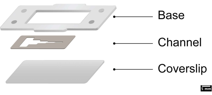
Figure 1: Schematic showing the assembly of the layers. This figure was adapted with permission from Ahmed et al.38. Please click here to view a larger version of this figure.
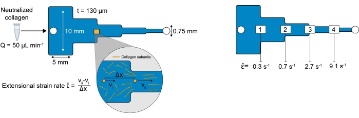
Figure 2: Stepped channel and extensional strain rates. (A) Schematic of the stepped channel with dimensions. Outset shows the calculation of the extensional strain rate. The extensional strain rate in each constriction is calculated from the velocity measured using particle image velocimetry (PIV). (B) The extensional strain rates in each constriction. This figure was adapted with permission from Ahmed et al.38. Please click here to view a larger version of this figure.
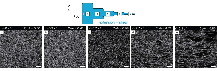
Figure 3: Confocal reflectance images of COL1 fibers in each microchannel segment after COL1 polymerization. The increase in the degree of fiber alignment from segment (a) to segment (e) can be visually observed. Scale bar = 25 µm. This figure was adapted with permission from Ahmed et al.38. Please click here to view a larger version of this figure.
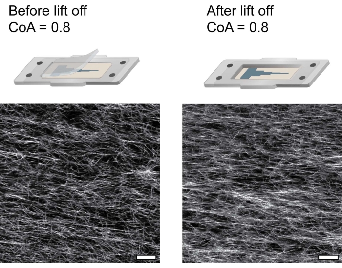
Figure 4: Confocal reflectance images of COL1 fibers showing that the fiber alignment remains unaffected by removing the channel cover. Scale bar = 25 µm. This figure was adapted with permission from Ahmed et al.38. Please click here to view a larger version of this figure.
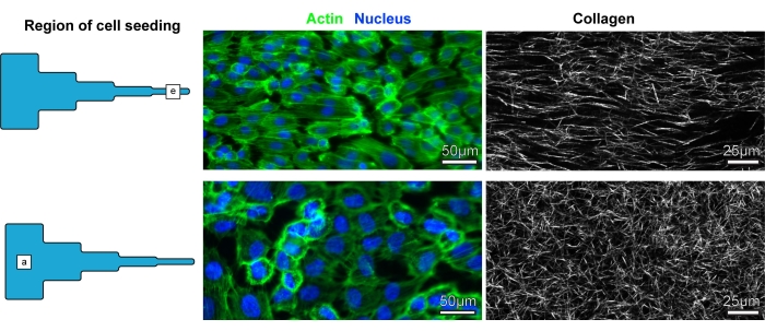
Figure 5: Representative images of cells and COL1 fibers. Representative images of cells and COL1 fibers in segment (e) of the COL1 matrix and segment (a) of the COL1 matrix. Please click here to view a larger version of this figure.
Supplementary Figure 1: Figure showing laser-cut components with dimensions. (A) Channel, (B) magnetic base, and (C) channel cover mold. All dimensions in millimeters. Please click here to download this File.
