JoVE Educazione Scientific
Aeronautical Engineering
È necessario avere un abbonamento a JoVE per visualizzare questo.  Accedi o inizia la tua prova gratuita.
JoVE Educazione Scientific Aeronautical Engineering
Nozzle Analysis: Variations in Mach Number and Pressure Along a Converging and a Converging-diverging Nozzle
  • 00:01Concepts
  • 03:48Measuring Axial Pressure in Converging and Converging-Diverging Nozzles
  • 06:28Risultati

Analisi degli ugelli: variazioni del numero di Mach e della pressione lungo un ugello convergente e un ugello convergente-divergente

English

Condividere

Panoramica

Fonte: Shreyas Narsipur, Ingegneria meccanica e aerospaziale, North Carolina State University, Raleigh, NC

Un ugello è un dispositivo comunemente usato per accelerare o decelerare il flusso in virtù della sua sezione trasversale variabile. Gli ugelli sono ampiamente utilizzati nei sistemi di propulsione aerospaziale. Nei razzi, il propellente che viene espulso dalla camera viene accelerato attraverso un ugello per creare una forza di reazione che spinge il sistema. Nei motori a reazione, un ugello viene utilizzato per trasformare l’energia da una fonte ad alta pressione in energia cinetica dello scarico per produrre spinta. Il modello isentropico lungo l’ugello è sufficiente per un’analisi di primo ordine in quanto il flusso in un ugello è molto rapido (e quindi adiabatico ad una prima approssimazione) con perdite di attrito molto piccole (perché il flusso è quasi unidimensionale con un gradiente di pressione favorevole, tranne se si formano onde d’urto e gli ugelli sono relativamente brevi).

In questo esperimento, due tipi di ugelli sono montati su un banco di prova dell’ugello e viene creato un flusso di pressione utilizzando una fonte di aria compressa. Gli ugelli vengono eseguiti per diverse impostazioni di contropressione per analizzare il flusso interno negli ugelli in condizioni di flusso variabili, identificare i vari regimi di flusso e confrontare i dati con le previsioni teoriche.

Principi

Procedura

In questa dimostrazione è stato utilizzato un banco di prova dell’ugello, che consisteva in una sorgente di aria compressa che incanala l’aria ad alta pressione attraverso gli ugelli da testare, come mostrato nella Figura 5. La pressione di flusso varia da 0 a 120 psi ed è controllata tramite una valvola meccanica. Mentre le pressioni vengono misurate utilizzando un sensore esterno, le portate di massa nell’ugello vengono misurate da una coppia di rotametri posizionati proprio prima dello …

Risultati

The following constants were used in the analysis: specific heat of dry air, γ: 1.4; reference nozzle area, Ai = 0.0491 in2, and standard atmospheric pressure, Patm = 14.1 psi. Figures 8 and 9 show the variation in pressure ratio and Mach number across the length of the nozzle (normalized based on total nozzle length) for various back-pressure settings for the converging and converging-diverging nozzles, respectively. The mass flow parameter versus the back-pressure ratio is also plotted and studied for both the nozzles.

From Figure 8, we observe that as the pB/pratio decreases(until 0.5283), flow at every section of the nozzle is subsonic and increases with decreasing area. At and below pB/pO = 0.5283, the Mach number at the throat (normalized nozzle distance = 0.93) does not exceed one. This clearly demonstrates that the flow is choked at the throat. Beyond the throat/nozzle exit, there is uncontrolled expansion of the flow, leading to supersonic Mach numbers. The overall trends in p/pO distribution matches theoretical trends from Figure 3. The trends in MFP follow theoretical results until pB/pO = 0.6 but start decreasing instead of plateauing for lower values of back-pressure ratios. Given that the flow is choked, the MFP should be constant. However, based on the location of the tap measuring the throat pressure (tap 9, Figure 6), we see that the measurements are taken slightly before the true nozzle throat that in turn leads to an incorrect measurement of the MFP.

For the converging-diverging nozzle (Figure 9), subsonic flow is observed until p/pO at the throat (normalized nozzle distance = 0.68) equals 0.5283 (choked flow condition). Further reduction of pB/pO shows three distinct patterns:
a. Pattern 1 – Flow reaches choked condition at the throat and decelerates subsonically in the diverging section (0.8 < pB/p< 0.7).
b. Pattern 2 – Flow accelerates supersonically beyond the throat, forms a shock in the diverging section, and decelerates (in some cases to subsonic velocities) for 0.7 < pB/p< 0.3.
c. Pattern 3 – Flow continues to accelerate supersonically for the entirety of the diverging section for pB/pvalues lower than 0.3.

The MFP increases with decreasing back-pressure ratios, peaks at pB/p= 0.5, and starts decreasing instead of remaining constant as predicted by theory.


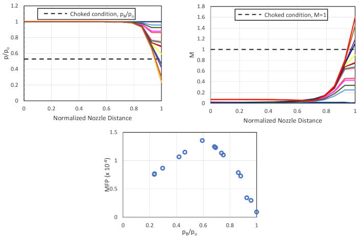
Figure 8. Results for the converging nozzle (from top-right, clockwise) variation in pressure ratio across the nozzle; variation in Mach number across the nozzle; and variation in mass plow parameter with back-pressure ratio. Please click here to view a larger version of this figure.

Applications and Summary

Nozzles are commonly used in aircraft and rocket propulsion systems as they offer a simple and effective method to accelerate flow in restricted distances. In order to design nozzles to suit a given application, an understanding of the flow behavior and factors that affect said behavior for a range of flow conditions is essential for designing efficient propulsion systems. In this demonstration, the converging and converging-diverging nozzles – two of the most common nozzle types used in aerospace applications – were tested using a nozzle test rig. The pressure and Mach number variations across the two nozzles were studied for a wide range of flow conditions.

Results for the converging nozzle tests showed that the maximum limit up to which flow can be accelerated is M = 1, at which point flow at the nozzle throat gets choked. Once flow is choked, any increase in inlet flow velocity did not increase the flow velocity at the throat/exit to supersonic speeds. Analysis of the converging-diverging nozzle provides insight into how supersonic flow velocities can be achieved once flow gets choked at the throat. We also observed three types of flows that can be obtained after the choked throat depending on the back-pressure ratio of the flow. A comparison of the pressure trends obtained for both the converging and converging-diverging type nozzles with theoretical results was excellent. However, the experimental results showed the mass flow parameter decreasing for lower values of back-pressure ratio instead of plateauing once the maximum value was achieved, as predicted by theory. 


Figure 9. Results for the converging-diverging nozzle (from top-right, clockwise) variation in pressure ratio across the nozzle; variation in Mach number across the nozzle; and variation in mass plow parameter with back-pressure ratio. Please click here to view a larger version of this figure.

Trascrizione

A nozzle is a device that is commonly used in aerospace propulsion systems to accelerate or decelerate flow using its varying cross section.

The most basic type of nozzle, the converging nozzle, is essentially a tube with an area that gradually decreases from the entry to the exit, or throat. As the nozzle area decreases, the flow velocity increases, with the maximum velocity occurring at the throat. As the inlet flow velocity increases, flow velocity at the throat also increases until it reaches Mach 1. When it reaches Mach 1, the flow at the throat is choked, meaning that any further increase of the inlet flow velocity does not increase the flow velocity at the throat. For this reason, converging nozzles are used to accelerate fluids in the subsonic regime alone.

The flow in a nozzle is caused by a variation in pressure between two points. Here, the pressure at the exit is referred to as the back-pressure, and the pressure at the entry is the stagnation pressure. The ratio between them is the back-pressure ratio, which can be used to control flow velocity. When the stagnation pressure equals the back-pressure, there is no flow.

Let’s look at the Mach number across the length of the nozzle. For the no flow condition, when the back-pressure ratio is equal to one, the Mach number is obviously zero. As back-pressure is decreased, the flow velocity along the converging section increases, as well as the Mach number, with its peak value at the throat. When the back-pressure ratio reaches a value of 0.5283, the Mach number at the throat is one and the flow is choked. As the back-pressure is further reduced, the Mach number at the throat stays constant at one.

Another common nozzle is the converging-diverging nozzle, which has a section of decreasing area, followed by a section of increasing area. We can also look at the Mach number across the length of the converging-diverging nozzle to examine flow conditions at varying back-pressure ratios. For the no flow condition, again the Mach number is zero.

As the back-pressure decreases, the Mach number increases across the converging section while decreasing across the diverging section. When the throat pressure ratio approaches 0. 5283, the flow becomes choked and it reaches Mach one before decreasing subsonically. As the back-pressure is further reduced, the flow after the throat goes supersonic and then subsonic.

At very low back-pressure ratios, the flow isentropically expands and remains supersonic throughout the diverging nozzle, reaching Mach numbers greater than one. Alternatively, the flow can form a shock when it expands in the diverging section.

If the pressure at the nozzle exit is lower than the ambient pressure, the jet exiting the nozzle is highly unstable with variations in pressure and velocity. This is called over-expanded flow. If the pressure at the nozzle exit is higher than the ambient pressure, the flow exhibits similar unstable flow and is called under-expanded.

In this experiment, we will demonstrate and analyze flow in both a converging and a converging-diverging nozzle.

In this experiment, we will study the behavior of nozzles using a nozzle test rig, which consists of a compressed air source that channels the high-pressure air through the nozzles being tested. The flow pressure ranges from 0 – 120 psi and is controlled using a mechanical valve. The pressures are measured using an external sensor, and the mass flow rates are measured by a pair of rotameters connected in series right before the nozzle exhaust. Both of the nozzles tested have 10 ports, enabling pressure measurements throughout the length of the nozzle.

To begin the experiment, mount the converging nozzle in the center of the nozzle test rig. Then, use high-pressure PVC tubing to connect the 10 static pressure ports to the pressure measurement system, as well as the stagnation pressure port. Connect the pressure measurement system to the data acquisition interface to collect real-time data readings.

Now, take the zero flow condition pressure reading. Open the mechanical valve to start airflow. Then, adjust the flow using the mechanical valve in order to obtain a back-pressure ratio of 0.9. Record the stagnation pressure and atmospheric pressure from the pressure measurement system and the temperature from the temperature sensor. Record the gauge pressure of each pressure tap, making sure to note the tap number, axial position, and nozzle area ratio for each one based on geometry provided by the manufacturer.

Once the mass flow rate values are entered, push the ‘Record Data’ button to record all the readings at the set back-pressure ratio. Decrease the back-pressure ratio in steps of 0.1, down to a ratio of 0. 1, recording the measurements at each increment like before. Make sure to capture data at a back-pressure ratio of 0.5283, which is the theoretical choked flow condition.

When these tests have been completed, turn off the airflow, disconnect the PVC tubing, and replace the converging nozzle with the converging-diverging nozzle. Connect the ports to the measurement system, then repeat all of the measurements as described previously.

To analyze our data, first we calculate the pressure ratio across the nozzle using the static pressure measurement at each port. Recall that the back-pressure measurement was made at port 10. We can also calculate the Mach number at each port using this equation, where gamma is the specific heat.

Here, we’ve plotted the variation in pressure ratio and Mach number versus the normalized nozzle distance for each flow rate in our converging nozzle. At the throat, the Mach number does not exceed 1, meaning that the flow is choked. However, it should be noted that the data at the throat corresponds to port 9, which is slightly before the actual throat. Beyond the throat exit, there is uncontrolled expansion of the flow, leading to supersonic Mach numbers.

Next, using the data collected, we can calculate the mass flow parameter, MFP, using the equation shown. Here, m-dot is the mass flow rate through the nozzle, T-zero is the stagnation temperature, AT is the area of the throat, and p-zero is the stagnation pressure. The MFP increases with decreasing back-pressure ratio up until 0.6, which corresponds to expected behavior, as mass flow should increase as the back-pressure ratio decreases.

The MFP should then remain constant after 0.6, as the flow is choked at this point and the mass flow cannot increase. However, we observe a decrease in MFP in this region. This result is likely caused by the location of the tap measuring throat pressure, which is slightly before the true nozzle throat. This could be the most likely reason for the incorrect MFP reading.

Now, let’s take a look at the converging-diverging nozzle, starting with the plot of pressure ratio and Mach number versus normalized nozzle distance. Observations of the Mach number variation across the nozzle show subsonic flow until the pressure ratio at the throat equals the choked flow condition of 0.5283. After this point, three distinct patterns are observed as back-pressure ratio is further reduced.

First, flow reaches the choked condition at the throat and decelerates subsonically in the diverging section. Second, flow accelerates supersonically beyond the throat and then decelerates, in some cases to subsonic velocities. Finally, we see that flow continues to accelerate supersonically for the entirety of the diverging section for back-pressure ratios lower than 0.3.

Finally, the plot of MFP shows an increase with decreasing back-pressure ratios, which peaks at 0.5283. This result is expected as flow increases up to the choked condition. As with the converging nozzle, the MFP should remain constant after reaching the choked flow condition, but we observe a decrease due to the location of the throat pressure tap.

In summary, we learned how varying cross sections of nozzles accelerate or decelerate flow in propulsion systems. We then measured the axial pressure along a converging and a converging-diverging nozzle, to observe variations in Mach number and pressure to deduce the flow patterns.

Tags

Cite This
JoVE Science Education Database. JoVE Science Education. Nozzle Analysis: Variations in Mach Number and Pressure Along a Converging and a Converging-diverging Nozzle. JoVE, Cambridge, MA, (2023).