Almost all laser applications are in close relation with the management of the optical wavefront of light. In the paraxial approximation, the complex field associated with the laser radiation can be described by two terms, the amplitude and the phase. Having control over these two terms is necessary to modify both the temporal and the spatial structure of laser beams at will. In general, the amplitude and the phase of a laser beam can be properly changed by several methods including the use of optical components that range from single bulk lenses, beam splitters and mirrors to most complex devices like deformable mirrors or spatial light modulators. Here, we show a method for encoding and reconstructing the complex field of coherent laser beams, which is based on dual-phase hologram theory1, and the utilization of a common-path interferometer.
Nowadays, there exists a wide variety of methods to encode the complex fields of laser beams2,3,4,5. In this context, some well-established methods to produce phase and amplitude modulation rely on the use of digital holograms6. A common point in all these methods is the necessity of generating a spatial offset to separate the desired output beam from the zeroth-order coming from the reflection of light at the SLM display. These methods are basically off-axis (usually applying for the first diffraction order of the grating), employing phase grating not only to encode the phase, but also to introduce necessary amplitude modulation. In particular, amplitude modulation is performed by spatially lowering the grating height, which clearly degrades the diffraction efficiency. The hologram reconstruction process mostly gets an approximate, but not exact, reconstruction of the amplitude and phase of the desired complex field. Discrepancies between theory and experiment seem to appear from an inaccurate encoding of the amplitude information as well as other experimental issues happening during the spatial filtering of the first diffraction order or due to SLM pixilation effects. In addition, the intensity profile of the input beam can introduce restrictions on the output power.
In contrast, with the introduced method7, all light management is carried out on-axis, which is very convenient from an experimental point of view. Additionally, it takes advantage of considering, in the paraxial approximation, the complex field associated with laser beams as a sum of two uniform waves. The amplitude information is synthetized by the interference of these uniform waves. In practice, such interference is carried out by spatial filtering of light frequencies at the Fourier plane of a given imaging system. Previously, the phase patterns associated with the uniform waves are spatially multiplexed and encoded into a phase-only SLM (placed at the entrance plane of this imaging system). Hence, the whole optical setup can be regarded as a common-path interferometer (very robust against mechanical vibrations, temperature changes, or optical misalignments). Please, note that the abovementioned interference process can be alternatively accomplished by using other optical layouts: with a couple of phase-only SLMs properly placed within a typical two-arm interferometer, or by time sequentially encoding the two phase patterns into the SLM (previous introduction of a reference mirror in the optical setup). In both cases, there is no necessity of spatial filtering, and consequently no loss of spatial resolution, at the expense of increasing the complexity of the optical system, as well as the alignment process. Here, it should be also emphasized that by using this encoding method, the full spectrum of the desired complex field can be exactly retrieved at the Fourier plane, after filtering all diffraction orders but the zeroth one.
On the other hand, the efficiency of the method depends on several factors: the manufacturer's specifications of the SLM (e.g., fill factor, reflectivity, or diffraction efficiency), the size of the encoded pattern, and the way at which the light impinges onto the SLM (reflection with a small hitting angle, or normal incidence by using a beam splitter). At this point, under proper experimental conditions, the measured total light efficiency can be more than 30%. However, note that that the total light efficiency just due to the use of the SLM can be less than 50%. The lack of random or diffuser elements within the optical setup allows the retrieving of amplitude and phase patterns without coherent noise (speckle). Other significant aspects to point out are the utilization of a direct codification algorithm rather than iterative procedures and its ability to perform arbitrary and independent amplitude and phase modulation at the frequency refresh time of the SLM (up to hundreds of hertz according to the current technology).
In principle, the method7 is intended to be used with input plane waves, but it is not limited to that. For instance, if a Gaussian beam is hitting the SLM, it is possible to modify its irradiance shape at the output of the system by encoding a suited amplitude pattern into the SLM. However, as the intensity of the output beam cannot exceed that of the input beam at any transversal position (x,y), the shaping of the amplitude is performed by intensity losses originated by a partially destructive interference process.
The theory underlining the encoding method7 is as follows. Any complex field represented in the form U(x,y)= A(x,y)eiφ(x,y) can be also rewritten as:
 (1)
(1)
where
 (2)
(2)
 (3)
(3)
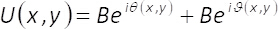
In equations 1-3, the amplitude and phase of the two-dimensional complex field U(x,y)is given by A(x,y) and φ(x,y), respectively. Note that, terms Amax (maximum of A(x,y)) and B = Amax/2 do not depend on the transversal coordinates (x,y). From the theory, if we set Amax=2, then B =1. Hence, the complex field U(x,y) can be obtained, in a simple manner, from the coherent sum of uniform waves Beiϑ(x,y) and Beiθ(x,y). In practice, this is accomplished with a common-path interferometer made up of a single phase element α(x,y), placed at the input plane of an imaging system. The single phase element is constructed by spatial multiplexing of the phase terms ϑ(x,y)
and θ(x,y) with the help of two-dimensional binary gratings (checkerboard patterns) M1(x,y) and M2(x,y) as follows
 (4)
(4)
hence,
 (5)
(5)
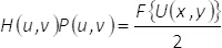
These binary patterns fulfill the condition M1(x,y) + M2(x,y) = 1. Note that, the interference of uniform waves cannot happen if we do not mix the information contained in the phase elementα(x,y). In the present method, this is carried out by using a spatial filter able to block all diffraction orders but the zeroth one. In this way, after the filtering process at the Fourier plane, the spectrum H(u,v)= F{eiα(x,y)} of the encoded phase function is related to the spectrum of the complex field F{U(x,y)} by the expression
 (6)
(6)
In Eq. (6), (u,v) denote coordinates in the frequency domain, P(u,v) holds for the spatial filter, whereas the Fourier transform of a given function Θ(x,y) is represented in the form F{Θ(x,y)}. From Eq. (6), it follows that, at the output plane of the imaging system, the retrieved complex field URET(x,y), (without considering constant factors), is given by the convolution of the magnified and spatially reversed complex field U(x,y) with the Fourier transform of the filter mask. That is:
 (7)
(7)
In Eq. (7), the convolution operation is denoted by the symbol  , and the term Mag represents the magnification of the imaging system. Hence, the amplitude and phase of U(x,y) is fully retrieved at the output plane, except for some loss of spatial resolution due to the convolution operation.
