Engineered tissues heavily rely on proper vascular networks to provide vital nutrients and gases and remove metabolic waste. In this work, a stepwise seeding protocol of endothelial cells and support cells creates highly organized vascular networks in a high-throughput platform for studying developing vessel behavior in a controlled 3D environment.
The cardiovascular system is a key player in human physiology, providing nourishment to most tissues in the body; vessels are present in different sizes, structures, phenotypes, and performance depending on each specific perfused tissue. The field of tissue engineering, which aims to repair or replace damaged or missing body tissues, relies on controlled angiogenesis to create a proper vascularization within the engineered tissues. Without a vascular system, thick engineered constructs cannot be sufficiently nourished, which may result in cell death, poor engraftment, and ultimately failure. Thus, understanding and controlling the behavior of engineered blood vessels is an outstanding challenge in the field. This work presents a high-throughput system that allows for the creation of organized and repeatable vessel networks for studying vessel behavior in a 3D scaffold environment. This two-step seeding protocol shows that vessels within the system react to the scaffold topography, presenting distinctive sprouting behaviors depending on the compartment geometry in which the vessels reside. The obtained results and understanding from this high throughput system can be applied in order to inform better 3D bioprinted scaffold construct designs, wherein fabrication of various 3D geometries cannot be rapidly assessed when using 3D printing as the basis for cellularized biological environments. Furthermore, the understanding from this high throughput system may be utilized for the improvement of rapid drug screening, the rapid development of co-cultures models, and the investigation of mechanical stimuli on blood vessel formation to deepen the knowledge of the vascular system.
The field of tissue engineering is rapidly progressing towards the fabrication of engineered constructs to replace missing or damaged organs and tissues1. However, fully functional constructs have yet to be achieved, in part, since generating operational vascular networks for tissue nourishment remains an outstanding challenge. Without proper vascularization, engineered tissues are limited to a passive diffusion transport of oxygen and nutrients, constraining the maximum viable tissue thickness to the diffusion limit, approximately 200 µm2. Such thicknesses are not suitable to repair large tissue defects or for full organ fabrication, which renders the presence of functional vascular network a mandatory characteristic for functional and implantable tissues3.
The vascular system is comprised of a wide variety of blood vessels, with different sizes, phenotypes, and organization, tightly related to the host tissue. Understanding the behavior, response and migration decisions made by the developing and sprouting vessels can instruct their integration in engineered tissues4. Currently, the most common approach for creating in vitro vascular networks is combining endothelial cells (ECs) with support cells (SCs, with the capability to differentiate into mural cells), seeded within a three-dimensional micro-environment. This environment provides chemical and physical cues to allow the cells to attach, proliferate and self-assemble into vessel networks2,5,6,7,8. When co-cultured, SCs secrete extracellular matrix (ECM) proteins while providing mechanical support to the ECs, which form the tubular structures. Furthermore, a cross-interaction between both cell types promote tubulogenesis, vessel sprouting and migration, in addition to the SCs maturation and differentiation into α-smooth muscle actin-expressing (αSMA) mural cells4. Vessel network development is most commonly studied in 3D environments created using hydrogels, porous polymeric scaffolds, or a combination thereof. The latter option equally provides a cell-friendly environment and the required mechanical support for both the cells and the ECM9.
A great amount of work has been carried out to study vascular development, including co-culturing the cells on hydrogels10, hydrogels-scaffold combinations11,12, 2D platforms, and microfluidic devices13. However, hydrogels can be easily deformed by the cell-exerted forces14, while 2D and microfluidics systems fail to recreate a closer-to-nature environment to obtain a more extrapolatable response15,16. Understanding how forming vessels react to their surrounding environment can provide critical insight that might allow for the fabrication of engineered environments with the capability of guiding the vessel development in a predictable manner. Understanding vascular formation phenomena is especially critical to keep pace with the rapid emergence of submicron-to-micron scale fabrication techniques, such as stereolithography, digital projection lithography, continuous liquid interface production, 3D melt-electro jetwriting, solution based 3D electro jet writing, and emerging bioprinting techniques17,18,19,20,21. Aligning the control of these micromanufacturing techniques with a deepened understanding of vascular biology is key to the creation of an appropriate engineered vasculature for a target tissue.
Here, we present a 3D system to study the response of new forming and sprouting vessels to the surrounding scaffold geometry, observing their sprout origin and subsequent migration22. By utilizing 3D scaffolds with tessellated compartment geometries, and a two-step seeding technique, we succeeded to create highly organized vascular networks in a clear and easy to analyze fashion. The tessellated geometries provide a high throughput system with individual units containing vessels that respond to their local environment. Using multicolored ECs, we tracked sprout formation origins and subsequent migration patterns, correlated to the compartment geometry and the SCs location22.
Although the proposed protocol has been prepared to analyze the effects of geometrical cues on vascularization behavior, this approach can be expanded and applied to a variety of new applications. The tessellated scaffold and the easily imageable networks allow for the straightforward analysis of different ECs and SCs interaction, the addition of specific organ cells and their interaction with the vascular networks, drug effect on vascular networks, and more. Our suggested system results very versatile and of simple fabrication and processing.
1. Tessellated scaffold fabrication
NOTE: Photolithography is a widespread technique that requires specialized equipment typically housed within a nanofabrication facility/laboratory. The method laid out in this protocol was generalized as much as possible for the audience; however, slight changes to procedures may be necessary depending on equipment available to the reader. We recommend performing these procedures in a clean room at a nanofabrication facility to ensure the highest process quality. Before beginning, obtain access to a mask-aligner (or some UV-exposure set-up), a spin coater, hot plates, a solvent washing station, a photomask, and a plasma cleaner. The solvents and chemicals used in procedure are hazardous, so please take the upmost care to avoid any chemical exposure. When designing the photomask, identify what sized silicon wafers and photomasks are compatible with the spin-coater and mask-aligner. Additionally, the photoresist located toward edges of the silicon wafer is typically deformed from handling; hence, make the designs toward the center area of the wafer.
2. Scaffold fibronectin coating
3. Endothelial cells seeding
4. Support cell seeding and co-culture
5. Immunofluorescent staining for characteristic vascular markers
NOTE: The following steps can be performed in the same wells where the constructs were cultured. It is critical to always make sure that the solutions completely cover the scaffolds. Moreover, when possible, performing the steps on an orbital shaker is recommended, although not mandatory.
6. Scaffold confocal imaging and vessel development analysis
NOTE: The following steps can be performed on the fixed and stained scaffolds at the chosen final time point or, if fluorescent cells were used, during the cell culture period without the need to terminate the experiment. For the latter, it is recommended to set specific time points; this work shows day 0 (before SCs seeding), and days 1, 3, 5 and 7 after SCs seeding (Figure 3A).
7. Time lapse imaging for sprouting origin detection and migration tracking
The presented protocol, using stereolithography techniques, allows for the fabrication of tessellated scaffolds made of SU-8 photoresist. Scaffolds with distinct compartment geometries (squares, hexagons, and circles), and highly accurate and repeatable features were obtained (Figure 1).
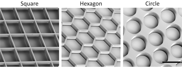
Figure 1: Representative scanning electron microscopy images of the tessellated square, circular, and hexagonal scaffold geometries (scale bar = 500 µm). Please click here to view a larger version of this figure.
With a stepwise cell seeding (steps 2 to 4), the fabricated scaffolds were used to create highly organized vascular networks. When using a traditional simultaneous seeding of both ECs and SCs, the resulting vessels lacked a clear organization. For this, the scaffold fibronectin coating was performed (step 2), the scaffold endothelialization step was skipped (step 3), and the DPSC and HAMEC were simultaneously co-seeded in fibrin gel (step 4). In this fashion, the cells are homogeneously distributed over the scaffold (Figure 2, top row), resulting in unpredictable and disorganized developed vascular networks that do not seem to interact with the surrounding scaffold. Contrarily, firstly seeding the ECs on the scaffold walls provides an accurate initial endothelial cell patterning. The later addition of SCs within a fibrin gel results in a predictable tubulogenesis phenomenon, with forming vessels closely following the shape of the scaffold wall, and sprouting new vessels migrating into the compartment space (Figure 2, bottom row).
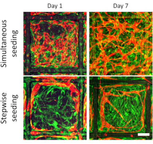
Figure 2: Vascularization comparison between simultaneous vs. stepwise cell seeding. Representative images of vascular development in tessellated scaffolds for a simultaneous (top row) cell seeding of ECs (red) and SCs (green), and step-wise cell seeding (bottom row) at days 1 and 5. The stepwise seeding results in organized vascular networks that follow the scaffold walls and sprout into the compartment space (scale bar: 100 µm). Please click here to view a larger version of this figure.
When using fluorescent ECs, either transfected or dyed, the vessels can be imaged in real time without the need to fix and terminate the experiment for each time point. Red fluorescent protein expressing ECs (RFP-ECs) were cultured on hexagonal scaffolds and imaged after seeding (Figure 3A, day 0). At day 1, the SCs were added and the vascular networks were imaged every other day to quantify the vessel development (Figure 3A, days 1, 3, 5 and 7). For each time point, wide images of the whole scaffold were taken (Figure 3B). For every compartment, the vessels mainly organized and interacted with cells located within their confinement. Hence, each compartment was isolated and the superfluous vessels outside the compartment were removed using ImageJ. The clean, single-compartment images were then analyzed using Angiotool. Angiotool returned a spread sheet file containing several vessel parameters, and a visual representation of the main network characteristics, such as skeleton, intersection points, and vessel surface. The obtained data was analyzed using the statistical analysis software Prism, and a clear vessel growth was observed for total vessel length and area during the experiment time frame (Figure 3C). During a 1-week experiment, vessels are expected to further develop and extended as shown in Figure 3A and Figure 2C. Decreasing vessel length or area, failure to form vessels by day 3 or vessels forming as shown in the top row of Figure 2 can be interpreted as a failed experiments.
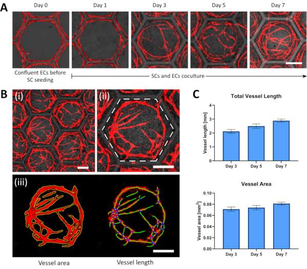
Figure 3: Representative development images and analysis of organized vascular networks. (A) ECs (red) reach confluence on the scaffold wall on which SCs are afterwards seeded; the SCs addition represents day 0 of the experiment. At day 1 after the SCs seeding, the ECs detach to the compartment space and start forming vessels that will continue sprouting and connecting at further days. (B) Confocal image processing steps for vascular network analysis (i) A wide confocal image containing several compartments is taken, (ii) a single compartment is cropped (demarked by the white dashed hexagon), (iii) then the vascular network channel is separated, and all vessels outside the compartment walls are cropped out. The single compartment image is analyzed using Angiotool, returning a list of vascular parameters complemented with visual markers, such as the vessel area (outlined in yellow), the vessels length (displayed with green lines), and the intersection points (marked as blue dots). (C) Comparative results of the total vessel length and the total vessel area within hexagonal compartments at different time points (results are presented as mean ± SD, n > 6; all scale bars: 200 µm). Please click here to view a larger version of this figure.
Using multicolored ECs to facilitate single cell identification, a confocal imaging time lapse was performed to allow single vessel tracking (Supplementary Video 1). The vessels were observed and tracked using the Manual Tracking ImageJ plugin. The tip cell was selected for each frame of the movie (Figure 4A) until the vessel anastomosed with the surrounding vasculature. As a result, the Manual Tracking plugin generated the vessel path in real time, which allowed to observe the vessel migration (Figure 4B).
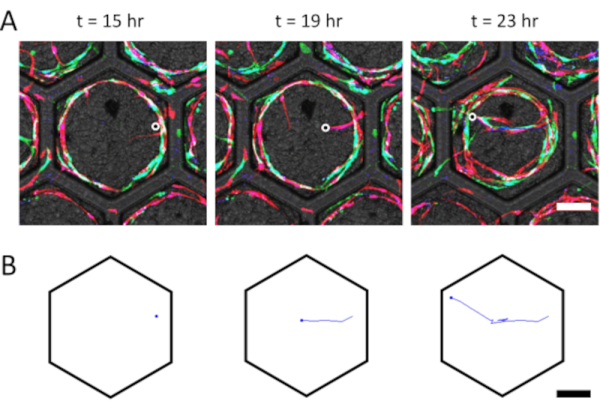
Figure 4: Representative sprouting vessel tracking. (A) A multicolored ECs (green, red, and blue) time lapse is used to facilitate single vessel identification. A sprouting vessel is identified and tracked using the ImageJ plugin Manual Tracking. The end side of the vessel is marked for every time point to track in real time; the black-in-white marker was added to show the selected vessel end point. (B) The resulting 2D tracking of the vessel, as processed by the ImageJ plugin, showing the farthest point with a dot, and the formed path with a line (scale bar = 200 µm). Please click here to view a larger version of this figure.
Vessel maturation, represented by the presence of SMA+ SCs, can be easily observed in the proposed platform. Vasculatures presenting higher numbers of SMA+ SCs represent a more mature network, since SMA expression correlates with vessel stabilization over time23. For the circular, hexagonal and squared compartments, the amount of SMA+ SCs increases over time (Figure 5A). By day 3, all shapes showed scattered SMA+ SCs and uncomplex vessels with few or no sprouts whatsoever. By day 7, all shapes showed a rich and complex vascular network, with a higher presence of SMA+ SCs surrounding the vessels. Furthermore, higher magnification images reveal a denser SMA+ SCs presence co-localized with formed vessels, evidencing the SCs recruitment and differentiation surrounding vascular structures (Figure 5B).
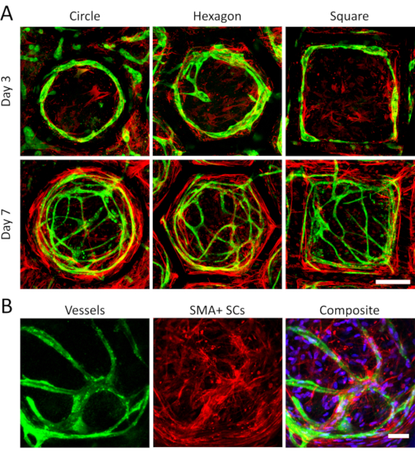
Figure 5: SMA+ SCs and blood vessels increase over time. A) Smooth muscle actin (red) and vWF (vessels, green) are shown for vascular networks in circular, squared and hexagonal compartments at day 3 and day 7. Both vasculature extension and SMA-expressing support cells (SMA+ SCs) increase over time, signifying a higher vessel maturation and complexity (scale bar = 200 µm). B) Representative images of the SMA+ SCs denser accumulation around vessels at day 7. The nuclei (blue) in the composite image reveal the presence of SCs not expressing the SMA protein (scale bar = 50 µm). Please click here to view a larger version of this figure.
Supplementary Video 1: multicolored ECs time lapse for vessel migration tracking. Please click here to download this video.
The need for a rich vasculature within embedded in engineered tissues is critical for construct survival and proper function1. Although engineering the vascular system has been the focus of a vast amount of research, much is left to investigate and understand24. In particular, when recreating a specific tissue, the microvasculature should behave and organize accordingly12. The most common approach for microvessels generation is co-seeding endothelial and support cells within a suitable 3D environment compatible for cell attachment, proliferation, and vessel formation25. This methodology often results in greatly unorganized networks, making it difficult to study the microvascular behavior22. Here, the presented protocol provides a new tool that generates highly organized vascular networks in a high-throughput system, with vessels that can be easily tracked and monitored through time, to study their development and behavior. The stepwise seeding of the ECs (step 2-3), followed by the SCs (step 4), are critical steps to achieve such organized networks22. Additionally, this technique presents a real 3D environment for vascular models, in which vessels can migrate in the three dimensions and create relevant structures. In contrast, more popular methods for vascular modelling, such as microfluidics systems, only offer a 2.5D tissue representation26.
The proposed method can be easily modified and applied to study many different factors affecting the vessel network development and behavior. Photolithographic SU-8 resin scaffold fabrication is a common technique with an impressive versatility that enables creating a wide variety of shapes26,27, with the potential to design structures resembling complex native constructs, such as the alveoli or the nephrotic unit. Nonetheless, a drawback of using SU-8 is its low bioabsorbability27, making the platform mainly a research tool, instead of an implantable tissue. However, this could be improved by utilizing biocompatible materials which can crosslink under UV/visible light illumination, and 3D printed using accurate techniques like stereolitography29. The resulting vascularized constructs could then be implanted in an animal model30. Another limitation of the system is the scaffold maximum achievable thickness with high detail accuracy, limited by the stereolithographic technique31. The proposed protocol is suitable for creating thin scaffold which might represent native tissue sizes.
This platform offers the potential to investigate several variables affecting the vascularization phenomena4,32. First, the interactions between different types of ECs and SCs, and their vessel formation, development and maturation capabilities, which are known to differ when using cells from different tissue origins33. Second, the effect of growth factors, small molecules, and inhibitors on the vasculature, allowing for a clear visualization of their impact in real time34,35. Third, the addition of other cell types, spheroids, or organoids and their communication and interaction with the forming vessels36. For this, the proposed system represents a powerful tool for investigating the microvascular system.
Future steps will take advantage of the proposed system to investigate the effect of mechanical stimuli, such as interstitial flow and mechanical stretching37,38, on the developing vasculature. This will hopefully shed light on new aspects that will expand the current knowledge and state-of-the-art research of the vascular mechanobiology.
The authors have nothing to disclose.
This research was supported by funding from the University of Michigan – Israel Partnership for Research. The authors would like to thank Uri Merdler, Lior Debbi and Galia Ben David for their great assistance and support, Nadine Wang, Ph.D. and Pilar Herrera-Fierro, Ph.D. of the Lurie Nanofabrication Facility at the University of Michigan, as well as Luis Solorio, Ph.D. for enlightening discussions of photolithography techniques.
Angiotool freeware | NIH-CCR | Free download at https://ccrod.cancer.gov/confluence/display/ROB2/Home | |
Bovine albumin serum Probumin | Millipore | 82-045-1 | |
Dental pulp stem cells | Lonza | PT-5025 | |
ECM media + bullet kit | Sciencell | #1001 | |
Ethanol 96% | Gadot-Group | 64-17-5 | |
Evicel fibrin sealant | Johnson&Johnson | EVB05IL | Provides both thrombin and fibrinogen (BAC2) solutions |
GlutaMAX | Gibco | 35050061 | |
Goat anti-mouse Cy3 antibody | Jackson | 115-166-072 | |
Goat anti-rabbit Alexa-Fluor 488 | Thermo- Fisher Scientific | A11034 | |
Human adipose microvascular cells | Sciencell | #7200 | |
Human fibronectin | Sigma | F0895-5MG | Stock concentration: 1 mg/mL |
ImageJ | NIH | Free download at https://imagej.nih.gov/ij/download.html | |
Isopropyl alcohol | Gadot-Group | 67-63-0 | |
Lift-off reagent | Kayaku Advanced Materials, Inc | G112850 | Commercial name Omnicoat |
Low-glucose DMEM | Biological Industries | 01-050-1A | |
Mouse anti-SMA antibody | Dako | M0851 | |
NEAA | Gibco | 11140068 | |
Paraformaldehyde solution 4% in PBS | ChemCruz | SC-281692 | |
Penicillin-Streptomycin-Nystatin Solution | Biological Industries | 03-032-1B | |
Phospate buffered saline (PBS) | Sigma | P5368-10PAK | |
Rabbit anti-vWF antibody | Abcam | ab9378 | |
Silicon wafer | Silicon Valley Microelectronics (SVM) | Wafers 4", Type N-1-10, 500-550 microns thick | |
SU-8 2050 photoresist | Kayaku Advanced Materials, Inc | Y11058 | |
SU-8 developer | Kayaku Advanced Materials, Inc | Y020100 | |
Tryton-X 100 | BioLab LTD | 57836 |