| 500 W diode laser system, 940 nm |
Laserline |
LDM 500 – 20 |
Pilot laser class 2 @ 650 nm, diode laser is a class 4 laser system –> special laboratory needed |
| Laser control box |
Laserline |
Laser control box LDM |
Add on to the laser system, used to switch electronically, laser threshold, shutter, laser on 0 V ..5 V TTL |
| Control box scanner |
Laserline |
|
Add on to the laser system, used to adjust the optical output power via analog signal from 0 V..10 V |
| Fiber Laser Mount 2", f = 80 mm |
Laserline |
|
Add on to the laser system |
| Multifunction Data Aquisition (DAQ) Device + BNC Terminal |
National Instruments |
NI-USB 6251 |
The DAQ card is used to trigger the IR camera, the DLP Light Commander 5500, control Laser and diode PDA 36A |
| Standard – PC |
|
|
Control PC – graphic card for two screens, at least 4 x USB, Windows based |
| BNC cabel |
|
|
Standard cable |
| HDMI cable |
|
|
Standard cable |
| Micro USB to USB cable |
|
|
Standard cable |
| LabVIEW 2013 SP1 Development System |
National Instruments |
|
Development environment for device control |
| LPPT control software |
BAM |
|
part of the LPPT software package by LabVIEW 2013 SP1 |
| LPPT intensity software |
BAM |
|
part of the LPPT software package by LabVIEW 2013 SP1 |
| LPPT laser control software |
BAM |
|
part of the LPPT software package by LabVIEW 2013 SP1 |
| Matlab 2016b |
MathWorks |
|
Postprocessing of the measurement data |
| LPPT postprocessing software |
BAM |
|
Postprocessing of the measurement data |
| IR camera control PC |
InfraTec |
|
Control PC is supplied by camera distributor |
| IR camera control software |
InfraTec |
Irbis 3 Professional |
|
| InfraTec SDK |
InfraTec |
|
Dynamic Link Library as interface between the native data aquisition format of Infratec and Matlab |
| IR camera |
InfraTec |
Image IR 8300 |
640 x 512, cooled InSb detector, wavelength 2 µm..5.7 µm, noise = 20 mK + accessories (LAN cable, Digital in/out cable, space ring, power supply, case) |
| Tripod |
Manfrotto |
161MK2B |
|
| IR camera mount |
Manfrotto |
405 |
|
| Projector development kit (PDK) for digital light processing (DLP) technology (DLP Light Commander 5500) |
Logic PD |
DLP-LC-DLP5500-10R |
DLP5500 Digital Micromirror Device from Texas Instruments included , light engine and case need to be disassembed |
| PDK control software |
Logic PD |
|
Included when delivered, DLP Light Commander control software |
| Mechanical platform for the PDK |
BAM |
|
Self made (140 x 230 x 420) mm |
| Power meter control unit |
Ophir |
Vega |
USB Interface |
| 30 W power meter head |
Ophir |
30(150)A-LP1-18 |
Power meter head to determine Transmission of the projector system |
| 500 W power meter head |
Ophir |
FL500A |
Power meter for process supervision |
| Motion controller |
Newport |
ESP301 |
with USB Interface |
| Translation stage |
Newport |
M-ILS200CC |
Connected to ESP301 |
| Photodiode with amplifier |
Thorlabs |
PDA 36A-EC |
1" mount |
| Reflective filter ND1 |
Thorlabs |
ND10A |
to be mounted to the PDA 36A |
| Pinhole 1" |
Thorlabs |
P1000S |
to be mounted to the PDA 36A |
| Optical aluminium breadboard |
Thorlabs |
MB60120/M |
(1200 mm x 900 mm) base |
| Plano Convex Lens f = 200 mm |
Thorlabs |
LA1979-B |
Coated for IR, first telescope lens |
| Plano Convex Lens f = 75 mm |
Thorlabs |
LA1145-B |
Coated for IR, second telescope lens |
| xy-translation stage |
Newport |
M401 |
Used for adjusting the telecope |
| Beamsampler |
Thorlabs |
BSF20-B |
Splits the optical output, used to reduce the optical input for the projector system |
| Mirror |
Thorlabs |
BB2-E03 |
Mirror for coupling the beam to the DLP Light Commander |
| Heavy duty lab jack |
Thorlabs |
L490 |
Used for the fiber mount and on top of the linear stage to position the sample (2x) |
| PDK-objective |
Nikon |
Nikon AF Nikkor 50 mm 1:1:8:D |
Objective for DLP Light Commander, 50 mm |
| Plano Convex Lens f = 100 mm |
Thorlabs |
LA1050 -B |
Lens is attached to the Nikon Objective |
| Bi-Convex Lens f = 60 mm |
Thorlabs |
LB1723 -B |
Lens to be attached to the Nikon objective in order to determine the optical transmission with the 30 W measurement head |
| Square protected gold mirror |
Thorlabs |
PFSQ20-03-M01 |
|
| High power IR sensor card |
Newport |
F-IRC-HP-M |
Sensor card to check the optical pathway |
| 2" crosshairs |
BAM |
|
Selfmade |
| 1" crosshairs |
BAM |
|
Selfmade |
| Bullseye level |
Thorlabs |
LCL01 |
|
| Translation Stage |
Newport |
M-UMR8.25 |
Used for measuring the beam profile |
| Micrometer screw |
Newport |
DM17-25 |
Used with translation stage M-UMR8.25 |
| Mounted Zero Aperture Iris |
Thorlabs |
ID75Z/M |
used to check the optical pathway |
| Bases and Post Holders Essentials Kit, Metric and Universal Components |
Thorlabs |
ESK01/M |
Basis |
| Posts & Accessories Essentials Kit, Metric and Universal Components |
Thorlabs |
ESK03/M |
|
| M6 Cap Screw and Hardware Kit |
Thorlabs |
HW-KIT2/M |
|
| Construction Rails |
Thorlabs |
XE25L700/M |
|
| 1" Construction Cube |
Thorlabs |
RM1G |
Used to mount construction rails |
| Electrical discharge machining |
Sodick |
AG60L |
www.sodick.de |
| St37 block of steel (100 x 100 x 40) mm |
BAM |
|
selfmade, hidden defect with remaining wall thicknesses of 0.25 mm, 0.5 mm, 0.70 mm 1.25 mm (shown in Fig. 5) |
| St37 block of steel (100 x 100 x 40) mm |
BAM |
|
selfmade, hidden defect with remaining wall thicknesses of 1 mm, 1.5 mm, 1.75 mm, 2 mm (shown in Fig. 5) |
| Graphite spray |
CRC Industries Europe NV |
GRAPHIT 33 |
Ref. 20760, 200 ml aerosol (Kontakt-Chemie) |
| Protective tape |
Tesa |
tesakrepp 4348 |
used to protect the hidden defects while coating |
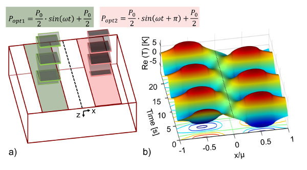
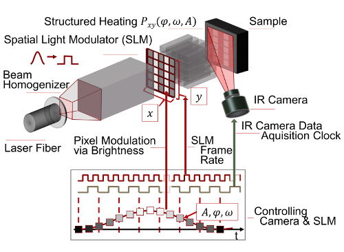
 通过其材料特性(热导率k ,热容c p和密度ρ )以及激发频率ƒ来描述。尽管热波强烈衰减,但它的波浪性质可以应用于获得样品性质的洞察力。首先应用热波干涉来确定层的厚度。与我们的方法相比,干涉效应用于深度尺寸( 即垂直于表面)参考“13。通过分割激光束将干扰思想扩展到第二维度,使用热波干涉来对地下缺陷进行调整14 ,仍然以传输方式应用该方法,这意味着它受到渗透的限制此外,由于仅使用一个激光源,该方法施加了建设性的干扰,这意味着无需参考,除了使用热波干扰的想法外,第一种技术方法是空间和Holtmann 等人使用具有内置光源的未经修改的液晶显示器(LCD)投影仪进行时间控制的加热,其光输出功率受到严格限制15.Pribe和Ravichandran的进一步接近旨在增加光学通过将激光器耦合到SLM 16来输出功率, s =“xref”> 17。