CAUTION: There is a risk of burns caused by hot soldering irons and heating cartridges. The heating cartridge should never be powered when not secured inside of the heating jacket. There is also a risk of pinching or lacerations from the moving 3D printer axis.
1. Overview and preparation
NOTE: Figure 1A shows a computer-generated rendering of the printer and Figure 1B is a photo of the finished printer.
- Procure all parts from the Table of Materials.
- See https://www.thingiverse.com/Addme/designs for all acrylic parts to be laser cut. Insure that 6 mm acrylic is used or the frame will not fit together. Laser cutters use a high energy laser to cut material; a professional shop is preferred here.
- See https://www.thingiverse.com/Addme/designs for all 3D-printed parts. It is important that the printing parameters specified with each part are used. Note that 3D printers have hot surfaces and moving parts, so use the help of a professional.
- Manufacture the heating jacket part, which is found at https://www.thingiverse.com/Addme/designs. If there is no available access to manufacturing capabilities, a silicone heater (Table of Materials) can be purchased with the associated 3D printed holder found at https://www.thingiverse.com/Addme/designs.
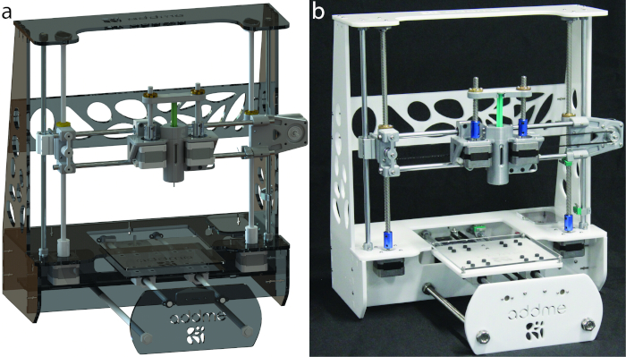
Figure 1: Additive manufacturing melt extrusion (ADDME) 3D printer. (A) Computer-generated rendering of the printer. (B) Photograph of a finished printer. Please click here to view a larger version of this figure.
2. Frame assembly
NOTE: The parts shown in Figure 2 are required to finish the frame assembly. The frame of the melt extrusion 3D printer is held together by a combination of 6 mm laser cut acrylic and M3 bolts and nuts (Figure 3). The bottom of the printer is further strengthened with a M10 threaded rod and nut combination.
- Gather acrylic parts 1–9 and place them together into the configuration shown in Figure 3A. Check the figure labels to ensure that each piece is located correctly. Secure with M3 screws and nuts in the configuration shown in Figure 3C using the M3 Allen key.
- Place the M10 threaded rod through the purpose made holes in acrylic members 6, 8, and 10. Secure them with M10 washers and nuts as shown in Figure 3B,D. Tighten with the variable spanner.
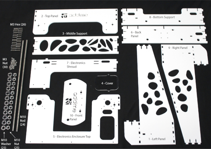
Figure 2: Components needed to assemble the frame. Please click here to view a larger version of this figure.
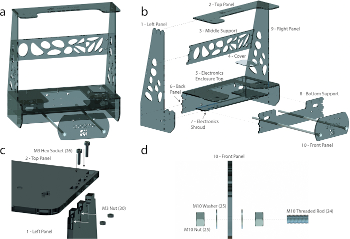
Figure 3: Frame assembly. (A) Assembled frame. (B) An exploded view with labeled acrylic parts and supporting M10 threaded rods. (C) An exploded view showing how each acrylic part is connected to one another, using M3 screws and nuts to hold the frame together. (D) An exploded view showing how the threaded rod holds acrylic parts 6, 8, and 9 together with M10 nuts and washers. Please click here to view a larger version of this figure.
3. Y-axis and printing bed sub-assembly
NOTE: The parts outlined in Figure 4 are required to finish the y-axis and printing bed sub-assembly. All screws are seen in Figure 4, and tools are listed in the Table of Materials.
- Using the parts in Figure 4, assemble the printing bed sub-assembly head according to Figure 5C.
- Slide two pillow blocks (19) onto each 8 mm shaft (21) according to Figure 5C. Slide the endstop (3DP 4) onto one of the 8 mm shafts (21) and secure the mechanical endstop (14) using M2 screws and an Allen key according to Figure 5E.
- Secure all four pillow blocks (19) to the mounting bed (acrylic part 12) using the M4 screws and Allen key (Figure 5C). Secure the belt clamp (3DP 3) onto the mounting bed (acrylic part 12) using the M3 screws and Allen key (Figure 5C). Secure the printing bed (acrylic part 11) onto the mounting bed (12) (Figure 5C) using the M3 screw, nut, and spring arrangement according to Figure 5F.
- Secure the remaining parts from Figure 4 to the frame according to Figure 5D,G.
- Secure two of the shaft holders (3DP 2) to both the back panel (acrylic part 6) and front panel (acrylic part 10) using the M2 screws and Allen key according to Figure 5D,G, respectively.
- Secure the stepper motor holder (12) to the back panel (acrylic part 6) using the M3 screws and Allen key (Figure 5D). Secure the stepper motor (11) to the stepper motor holder (12) using the M3 screws and Allen key (Figure 5D). Secure the belt idler (3DP 1) to the front panel (acrylic part 10) using the M3 screws and Allen key (Figure 5G).
- Place the printing bed sub-assembly into the frame by matching up each end of an 8 mm shaft (21) to a shaft holder (3DP 2) according to Figure 5A,D,G.
NOTE: It may be necessary to loosen the M12 washers on the front panel (acrylic part 10) to create space to place the printing bed sub-assembly into the frame. - Finally, to complete the y-axis and printing bed sub-assembly, screw the idler to the belt idler (3DP 1) by using an M3 screw, then secure the idler toothed to the stepper motor by tightening the M2 grub screw on the idler toothed with the M2 Allen key. Slide the belt (17) around the idler (17) and idler toothed (17) and into the belt clamp (3DP 3) to produce tension in the belt. Complete the section by tightening the belt clamp (3DP 3) with the M3 Allen key.
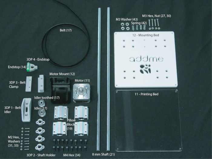
Figure 4: Components needed to put together the y-axis and printing bed sub-assembly. Please click here to view a larger version of this figure.
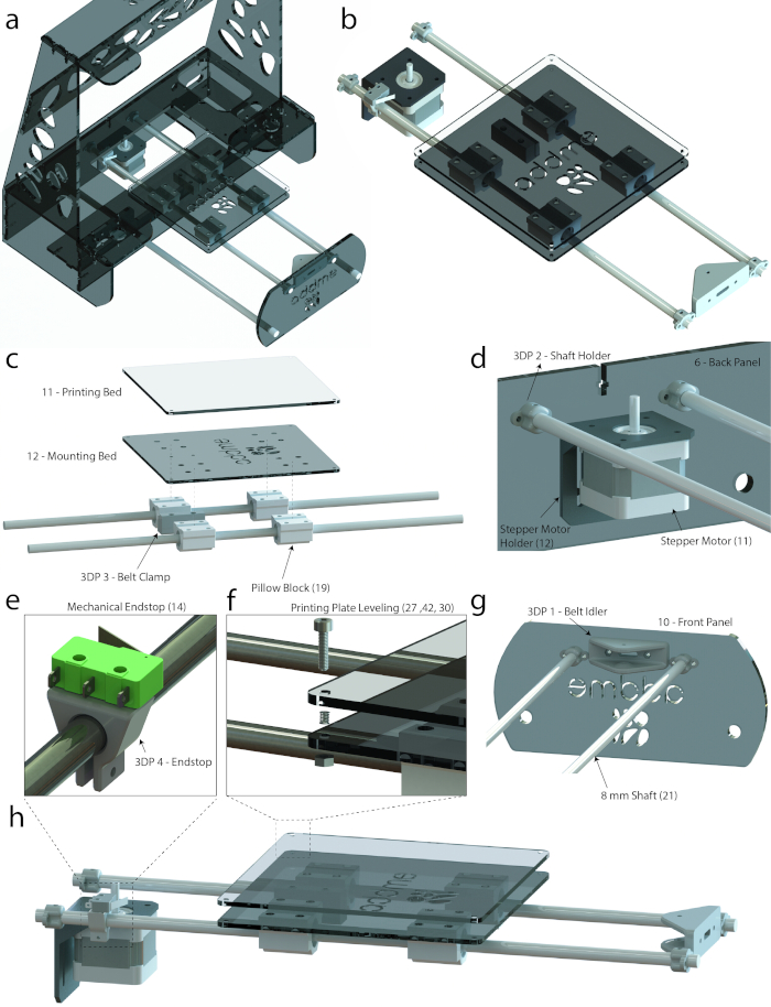
Figure 5: Additive manufacturing melt extrusion (ADDME) 3D printer. (A) Graphical rendering of the frame, y-axis, and bed. (B) Graphical rendering of the y-axis and bed. (C) Exploded view of the bed sub-assembly. (D) Labeled view showing how the y-axis connects to the back panel. (E) Zoomed-in view of the mechanical endstop. (F) Exploded view of the printing plate spring leveling system. (G) Labeled view showing how the y-axis connects to the front panel. (H) Side view graphical render of the y-axis and bed. Please click here to view a larger version of this figure.
4. X-axis sub-assembly
NOTE: The parts outlined in Figure 6 are required to finish the x-axis sub-assembly. All screws are seen in Figure 6, and tools are listed in the Table of Materials.
- Using the parts in Figure 6, assemble the left side of the x-axis sub-assembly according to Figure 7C.
- Place the brass nut (18) inside of the nut holder (3DP 5) and secure to the x-axis pillow left (3DP 8) using the M3 screws and Allen key (Figure 7C).
- Secure the pillow block (19) onto the x-axis pillow left (3DP 8) using the M4 screws and Allen key (Figure 7C). Secure the x-axis idler 1 (3DP 9) to the x-axis pillow left (3DP 8) using the M3 screws and Allen key (Figure 7C).
- Align the center holes of the idler (17), x-axis idler 1 (3DP 9), and x-axis Idler 2 (3DP 10). Secure using the M3 screws and Allen key (Figure 7C). Using the parts shown in Figure 6, assemble the right side of the x-axis sub-assembly according to Figure 7D.
- Place the brass nut (18) inside of the nut holder (3DP 5) and secure to the x-axis pillow right (3DP 6) using the M3 screws and Allen key (Figure 7D).
- Secure the pillow block (19) onto the x-axis pillow right (3DP 6) using the M4 screws and Allen key (Figure 7D). Secure the x-axis right (3DP 7) to the x-axis pillow right (3DP 6) using the M3 screws and Allen key (Figure 7D). Secure the stepper motor (11) to the x-axis right (3DP 7) using the M3 screws and Allen key (Figure 7D).
- Thread each of the threaded rods (18) into each of the brass nuts (18) according to Figure 7B. Slide two of the 8 mm shafts (20) into each of the pillow blocks (19) vertically, and two of the 8 mm shafts (20) horizontally according to Figure 7B,C,D.
- Secure the remaining parts from Figure 6 to the frame according to Figure 7E,F.
- Secure two of the shaft holders (3DP 2) to both the top panel (acrylic part 2) and electronics enclosure top (acrylic part 5) using the M2 screws and Allen key (Figure 7E,F). Secure the pillow block bearings (15) onto the top panel (acrylic part 2) using the M3 screws and Allen key (Figure 7E). Secure the stepper motors (11) onto the electronics enclosure top (acrylic part 5) using the M3 screws and Allen key (Figure 7F).
NOTE: The coupler (16) is a component that is designed to connect two different shaft sizes. - Secure the coupler (16) over the shafts of the stepper motors (11) by tightening the lower grub screw with the M2 Allen key (Figure 7F).
- Secure two of the shaft holders (3DP 2) to both the top panel (acrylic part 2) and electronics enclosure top (acrylic part 5) using the M2 screws and Allen key (Figure 7E,F). Secure the pillow block bearings (15) onto the top panel (acrylic part 2) using the M3 screws and Allen key (Figure 7E). Secure the stepper motors (11) onto the electronics enclosure top (acrylic part 5) using the M3 screws and Allen key (Figure 7F).
- Place the x-axis sub-assembly into the frame by aligning the vertical 8 mm shafts with the shaft holder (3DP 2) and tighten using the M2 screws and Allen key (Figure 7E,F). Secure the threaded rod (18) into the other end of the coupler (16) by tightening the upper grub screw with the M2 Allen key (Figure 7E,F).
NOTE: The top panel (acrylic part 2) may need to be temporarily removed so that the x-axis sub assembly can fit into the frame.
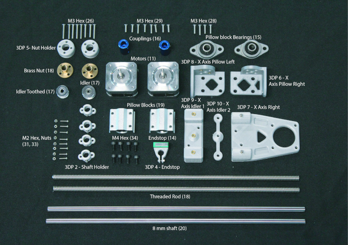
Figure 6: Components needed to put together the x-axis sub-assembly. Please click here to view a larger version of this figure.
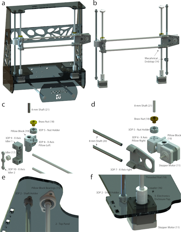
Figure 7: X-axis sub assembly. (a) Graphical rendering of the frame and x-axis. (b) Graphical render of the x-axis. (c) Exploded view of the left side of the sub assembly. (d) Exploded view of the right side of the sub-assembly. (e) Labeled view showing how the x-axis connects to the top panel. (f) Labeled view showing how the x-axis connects to the electronics enclosure. Please click here to view a larger version of this figure.
5. Extrusion sub-assembly
NOTE: The extrusion sub-assembly utilizes a dual stepper motor design to ensure that a high level of accuracy is achieved through the balancing of forces on each side of the plunger. The parts outlined in Figure 8 are required to finish the extrusion sub-assembly.
- Gather all parts shown in Figure 8 and assemble the extrusion head according to Figure 9.
NOTE: Figure 9B is an exploded view of the extruder sub-assembly that shows how each component fits together. The following steps explain how this is done. All screws are seen in Figure 8, and tools are listed in the Table of Materials.- Secure the two pillow blocks (19) onto the extruder backplate (3DP 14) using the M4 screws and Allen key (Figure 9B). Secure the extruder belt clamp (3DP 13) onto the extruder backplate (3DP 14) between the pillows blocks (19) using the M3 screws and Allen key (Figure 9B).
- Secure the extruder backplate (3DP 14) to the extruder motor holder (3DP 15) using the M3 hex screws and Allen key (Figure 9B). Secure the two stepper motors (11) onto the extruder motor holder (3DP 15) using the M3 hex screws and Allen key (Figure 9B).
NOTE: The coupler (16) is a component that is designed to connect two different shaft sizes. - Secure the couplers (16) over the shafts of the stepper motors (11) by tightening the lower grub screw with an M2 Allen key (Figure 9B). Secure the threaded screw (18) within the couplers (16) by tightening the upper grub screw (Figure 9B).
- Slide the heating jacket or silicone heater into the extruder motor holder (3DP 15) according to Figure 9B. Secure the brass nuts (18) inside plunger lock 1 (3DP 11) using the M3 screws and Allen key.
- Mount the extrusion head onto the x-axis according to Figure 9A.
- Slide the 8 mm shafts found on the x-axis into the pillow blocks (19) on the extruder head according to Figure 9A.
- Wrap the drive belt (17) through the idler (17) and idler toothed (17) located on the left and right x-axis assemblies and secure the drive belt (17) in the extruder belt clamp (3DP 13) using the M3 hex screws and Allen key (Figure 9C).
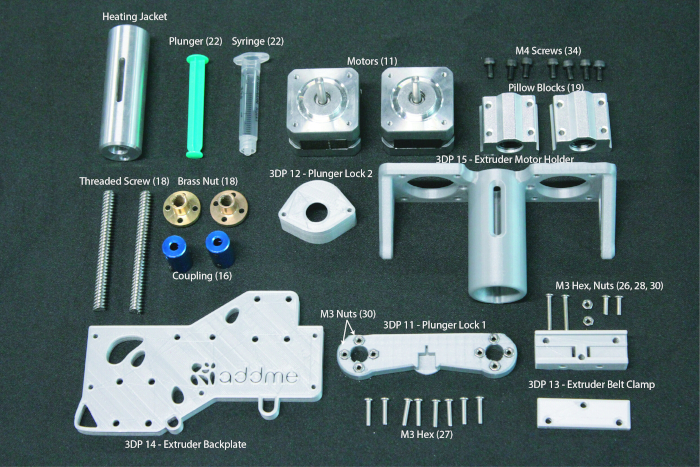
Figure 8: Components needed to assemble the extruder. Please click here to view a larger version of this figure.
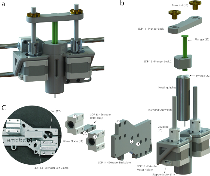
Figure 9: Extruder sub-assembly. (A) Graphical rendering of the extruder sub-assembly. (B) Exploded view showing extruder components. Please click here to view a larger version of this figure.
6. Electronics and wiring
- Mount the Arduino into acrylic part 7 (electronics shroud, shown in Figure 10A) with M3 hex screws using a M3 Allen key. Insert a ramps board on top of the Arduino board oriented as shown in Figure 10A,B with the USB plug facing acrylic part 6 (back panel).
- Mount the DC power supply jack in acrylic part 6 (back panel, as shown in Figure 10A) and connector to the power supply in Figure 10B. Connect the motor controllers, stepper motors, end stops, heater, and thermocouple to the respective pins (Figure 10B).
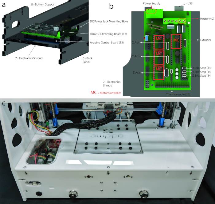
Figure 10: Electronics. (A) Graphical rendering of the electronics control board mounting location. (B) Connection diagram of electrical components and motors to 3D printing board [Jos Hummelink (grabcab.com) provided the Arduino and Ramps CAD files]. (c) Image of the finished wiring. Wires can be seen leading from the Ramps board, then to the extrusion head and x/y axis motors. Please click here to view a larger version of this figure.
7. Software, control, and calibration
NOTE: For more detailed instructions and troubleshooting information, see https://reprap.org/wiki/RAMPS_1.4.
- Download firmware from http://marlinfw.org/meta/download/.
- Install repetier https://www.repetier.com/.
- Replace the file .configuration in the firmware found in https://www.thingiverse.com/Addme/designs.
- Set buad rate in repetier to 112500 by navigating (in repetier) to Configure | Printer Settings | Connection | Baud Rate: 115200.
- Click the Connect icon in repetier.
- Once connected, full control over the printer is achieved. Navigate to Manual Control to move the printing bed and try setting the temperature.
CAUTION: Make sure that the maximum temperature of the syringe or housing components is not exceeded (see the discussion for more information). While the stepper motors have limited power, the movement of the axis presents a mechanical hazard.
NOTE: At this stage there is a fully operating printer. In the following section (section 8), the procedure for getting the printer ready for 3D printing is described.
8. Preparation for 3D printing
- Load a 2 mL syringe with the desired material, such as viscous cream, chocolate, or pluronic (Figure 11A).
- To place the syringe into the extrusion head, start by inserting the syringe into plunger lock 1 (3DP 11, Figure 11B). Next, insert the syringe into the heating jacket while carefully turning the threaded screws (Figure 11C).
- Optional: if the bed has not been leveled, it is necessary to level it. Move the printing head left and right then up and down, and check if the distance between the bed and syringe nozzle is consistent. Slide a piece of paper between the syringe and bed and feel the friction (Figure 11E), then use the M3 Allen key (Figure 11D) to adjust the bed level if required.
- Optional: if the chosen material needs to be heated, do this now. Navigate to the Manual Control tab in repetier and set the temperature to the desired level.
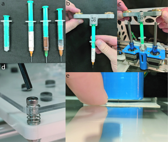
Figure 11: 3D printing preparation. (A) A 2 mL syringe loaded with (from left to right) viscous cream (150 mL, Nivea hand cream), chocolate (Cadbury, plain milk), and Pluronic F-127 (Sigma Aldrich). (B) Plunger being inserted into the plunger lock 1 (3DP 11). (C) Shown is a syringe being inserted into the heating jacket, while the threaded screws are catching on the brass nuts. (D) Shown is an Allen key about to be inserted into the retaining M3 hex screw, allowing the level to be adjusted. (E) A business card is then slid under the syringe to check the distance between the bed and syringe. Please click here to view a larger version of this figure.
The performance of ADDME during 3D printing was evaluated using a viscous cream (150 mL, Nivea hand cream), chocolate (Cadbury, plain milk), and Pluronic F-127 (Sigma Aldrich). The viscous cream and chocolate were used as is, and the Pluronic was dissolved into a 20% wt solution with ultrapure water and stored refrigerated at 5 °C until needed14,15.
Line testing involved printing a filament back and forth on the build plate in a basic pattern to evaluate individual filament properties such as thickness or consistency. Line tests were made with a series of movement commands called gcode as shown in Equation 1 below. The amount of material to extrude can be found using Equation 2. The printing parameters used can be found in Table 1, and results are shown in Figure 12A,B,C.

Equation 1: Representative line of gcode to control 3D printer movement, where: G01 tells the printer to conduct a linear move between the current position and the position specified by X, Y, and Z mm; E is the amount of material to extrude (mm) during this linear move; and F is the speed (mm/min).

Equation 2: Extrusion, where: E is the gcode value telling the extruder stepper motor how far down to push the syringe; and D is the distance that the printing head moves during the line of gcode.
To create complex 3D objects, we cannot manually input each line of code, which was done for line testing. To create complex 3D objects, the object to be printed must be inputted into a standard tessellation language (.stl) file into repetier and "sliced" into 3D printable gcode. It is critical that in the slicer configuration manager, the filament diameter is set to the size of the inner barrel diameter and the nozzle is set to the size of the syringe inner diameter. The full list of printing parameters is shown in Table 1, and results are shown in Figure 12D,E,F.
| Parameters | Line Testing | 3D Object | ||||
| Viscous Cream | Chocolate | Bioink | Viscous Cream | Chocolate | Bioink | |
| Syringe Inner Diameter (mm) | 0.33 | 0.84 | 0.33 | 0.33 | 0.84 | 0.33 |
| Barrel Inner Diameter (mm) | 9.35 | 9.35 | 9.35 | 9.35 | 9.35 | 9.35 |
| Temperature (°C) | Room Temp | 53 | Room Temp | Room Temp | 53 | Room Temp |
| Speed (mm/min) | 500 | 500 | 500 | 500 | 500 | 500 |
| Extrusion (scalar) | 100% | 200% | 150% | 100% | 200% | 150% |
| Syringe to Plate Distance (mm) | ~0.3 | ~1 | ~0.5 | ~0.3 | ~1 | ~0.5 |
Table 1: Printing parameters used throughout all tests.
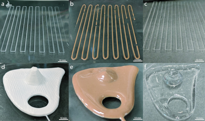
Figure 12: ADDME 3D printing results. (A) Line testing with viscous cream. (B) Line testing with chocolate. (C) Line testing with Pluronic F-127. (D) Custom-made object 3D-printed with viscous cream. (E) Custom-made object 3D-printed with chocolate. (F) Custom-made object 3D-printed with Pluronic F-127. Please click here to view a larger version of this figure.
To determine the dimensional accuracy of the ADDME printer in the X, Y, and Z directions when printing a semi-solid material, a 1 cm x 1 cm x 1 cm cube was printed, 3D-scanned, and dimensionally compared against the original cube CAD data. A viscous cream was used to print a 1 cm x 1 cm x 1 cm cube using a nozzle diameter of 0.33 mm (Birmingham Gauge needle 23), layer height of 0.33 mm, and infill of 15%. This cube was then scanned using a metrology rated 3D scanner (Artec Spider) capable of an accuracy up to 0.05 mm. The resulting data was compared using Cloud Compare (Open Source Project), 3D point cloud editing, and processing software.
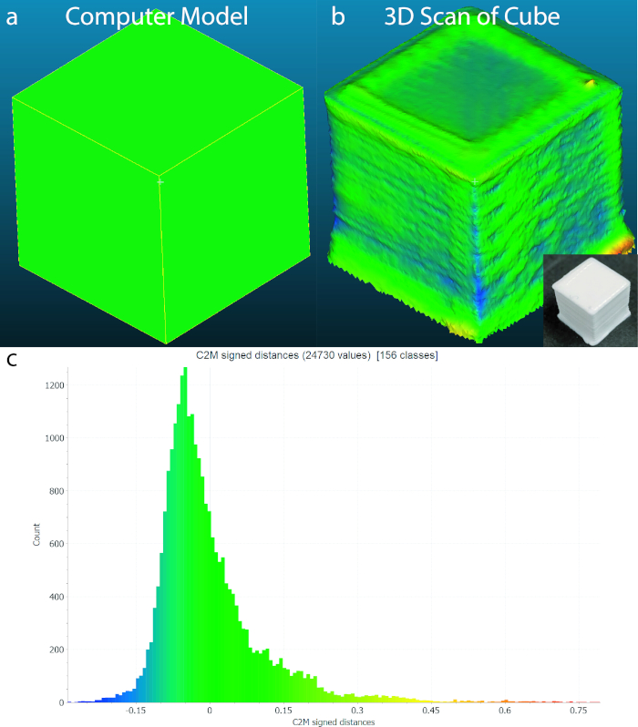
Figure 13: 3D Scanning Comparison. (A) The 1 cm x 1 cm x 1 cm cube made into a CAD model. (B) The 3D scan of the printed cube (inset). (C) The original model and 3D scan were then compared using cloud compare. A histogram of distances from nodes in the 3D model and scanned cube are presented. The C2M distances represent the physical differences between points in both models. Both models are within a tolerance of -0.15 mm and +0.15 mm. Please click here to view a larger version of this figure.
