하이드롤릭 점프
English
Share
Overview
출처: 알렉산더 S 래트너와 마디 나빌; 펜실베이니아 주립대학, 유니버시티 파크, 펜실베이니아 주 기계 및 원자력 공학과
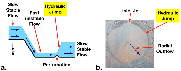
액체가 높은 속도로 열린 채널을 따라 흐르면 흐름이 불안정해질 수 있으며 약간의 장애가 발생하여 액체 상부 표면이 갑자기 더 높은 수준으로 전환될 수 있습니다(도 1a). 액체 레벨의 이러한 급격한 증가는 유압점프라고합니다. 액체 레벨의 증가는 평균 유량 속도의 감소를 야기한다. 그 결과 잠재적으로 파괴적인 유체 운동 에너지가 열로 소멸됩니다. 유압 점프는 댐 유출과 같은 대형 수작업으로 의도적으로 설계되어 손상을 방지하고 빠르게 움직이는 하천으로 인해 발생할 수 있는 침식을 줄입니다. 유압 점프는 또한 강과 개울에서 자연적으로 발생하며, 수꼭지에서 싱크대에 물의 방사형 유출과 같은 가정용 조건에서 관찰 될 수있다 (도 1b).
이 프로젝트에서는 오픈 채널 흐름 실험 시설이 건설됩니다. 수문게이트가 설치되며, 이는 업스트림 저수지에서 하류 유출로까지물의 배출 속도를 제어하기 위해 상승하거나 낮출 수 있는 수직 게이트입니다. 게이트 출구에서 유압 점프를 생성하는 데 필요한 유량은 측정됩니다. 이러한 사실 인정은 질량 및 모멘텀 분석에 근거를 둔 이론적인 값과 비교될 것입니다.

그림 1: a. 불안정한 고속도 흐름에 약간의 교란으로 인해 유출로에서 하류에서 발생하는 유압 점프. b. 가정용 수도꼭지에서 물의 방사형 유출에 유압 점프의 예.
Principles
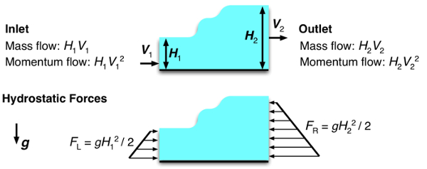
넓은 오픈 채널 흐름에서 액체는 낮은 고체 경계에 의해서만 제한되며 상부 표면은 대기에 노출됩니다. 질량 및 모멘텀의 입구 및 출구 수송의 균형을 맞추기 위해 열린 채널 흐름의 한 섹션에서 제어 볼륨 분석을 수행할 수 있다(도 2). 해당 액체 깊이 H 1 및 H2와 함께 제어 부피(V1 및 V2)의 입구및 출구에서 속도가 균일하다고 가정하면, 안정적인 질량 유량 균형이 감소합니다.
 (1)
(1)
이 제어 볼륨의 x-방향모멘텀 해석은 유입구 및 출구 모멘텀 유량(Eqn. 2)과 수압(유체 깊이로 인한)의 힘을 균형있게 합니다. 압력력은 대조군의 양면에서 안쪽으로 작용하며, 액체의 특정 중력(액체 밀도 시간 중력 가속: θg)과같으며, 각 면의 평균 액체깊이(H1/2, H2/2)를곱하여 각 측의 압력이 작용하는 높이를 곱한다(H1,H2). 이렇게 하면 Eqn. 2의 왼쪽에 이차적 표현이 생성됩니다. 각 측면을 통한 모멘텀 유량(Eqn. 2, 오른쪽)은 
 체액속도(V1, V2)를곱한 제어 부피를 통해 액체의 질량 유량과 동일하다.
 (2)
(2)
Eqn. 1V2를 제거하기위해 Eqn. 2로 대체 할 수 있습니다. 프로이드  수()는 또한 수압력에 유입유체 모멘텀의 상대적 강도를 나타내는 대체될 수 있다. 결과 식은 다음과 같이 명시할 수 있습니다.
 (3)
(3)
이 입방 방정식에는 세 가지 솔루션이 있습니다. 하나는 일반적인 오픈 채널 동작(입구 깊이 = 콘센트 깊이)을 제공하는 H1 = H2입니다. 두 번째 용액은 부정한 액체 수준을 제공하며, 이는 물리적이며 제거할 수 있습니다. 나머지 용액은 입구 프로드 수에 따라 깊이(유압 점프) 또는 깊이(유압 우울증)의 감소를 허용합니다. 입구 Froude 번호 (Fr1)가하나 보다 큰 경우, 흐름은 초임계 (불안정)라고하며 높은 기계적 에너지 (운동 + 중력 전위 에너지)를 갖는다. 이 경우 유압 점프는 자발적으로 또는 흐름에 약간의 방해로 인해 형성될 수 있습니다. 유압 점프는 기계적 에너지를 열로 방출하여 운동 에너지를 크게 줄이고 유량의 잠재적 에너지를 약간 증가시킵니다. 생성된 콘센트 높이는 Eqn. 4(Eqn. 3에 대한 용액)에 의해 제공됩니다. Fr1이 1> 경우 유동의 기계적 에너지를 증가시켜 열역학의 두 번째 법칙을 위반하는 경우 유압 우울증이 발생할 수 없습니다.
 (4)
(4)
유압 점프의 강도는 입구 프우드 번호로 증가합니다. Fr1이 증가함에 따라 H2/H1의 크기가 증가하고 인렛 운동 에너지의 더 큰 부분이 열 [1]으로 소멸됩니다.

그림 2: 유압 점프를 포함하는 오픈 채널 흐름의 섹션의 볼륨을 제어합니다. 단위 폭당 유입 및 아웃 질량 및 모멘텀 유량이 표시됩니다. 낮은 다이어그램에 표시된 단위 너비당 유수성 힘입니다.
Procedure
Results
Upstream Froude numbers (Fr1) and measured and theoretical downstream depths are summarized in Table 1. The measured threshold inlet flow rate for formation of a hydraulic jump corresponds to Fr1 = 0.9 ± 0.3, which matches the theoretical value of 1. At supercritical flow rates (Fr1 > 1) predicted downstream depths match theoretical values (Eqn. 4) within experimental uncertainty.
Table 1 – Measured upstream Froude numbers (Fr1) and downstream liquid depths for H1 = 5 ± 1 mm
| Liquid Flow Rate
( |
Upstream Froude Number (Fr1) | Measured Downstream Depth (H2) | Predicted Downstream Depth (H2) | Notes |
| 6.0 ± 0.5 | 0.9 ± 0.3 | 5 ± 1 | 5 ± 1 | Threshold Froude number for hydraulic jump |
| 11.0 ± 0.5 | 1.7 ± 0.5 | 11 ± 1 | 10 ± 2 | |
| 12.0 ± 0.5 | 1.9 ± 0.6 | 12 ± 1 | 11 ± 2 | |
| 13.5 ± 0.5 | 2.1 ± 0.6 | 14 ± 1 | 13 ± 2 |
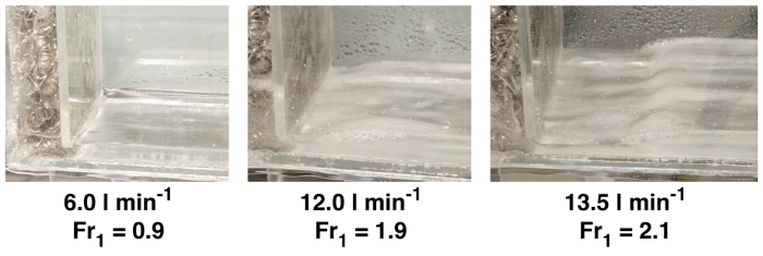
Photographs of the hydraulic jumps from the above cases are presented in Fig. 4. No jump is observed for  = 6.0 l min-1 (Fr1 = 0.9). Jumps are observed for the two other cases with Fr1 > 1. A stronger, higher amplitude, jump is observed at the higher flow rate supercritical case.

Figure 4: Photograph of hydraulic jumps, showing critical condition (no jump, Fr1 = 0.9) and jumps at Fr1 = 1.9, 2.1.
Applications and Summary
This experiment demonstrated the phenomena of hydraulic jumps that form at supercritical conditions (Fr > 1) in open channel flows. An experimental facility was constructed to observe hydraulic jump phenomena at varying flow rates. Downstream liquid depths were measured and matched with theoretical predictions.
In this experiment, the maximum reported inlet Froude number was 2.1. The pump was rated to deliver significantly higher flow rates, but resistance in the flow meter limited measurable flow rates to ~14 l min-1. In future experiments, a pump with a greater head rating or a lower pressure drop flow meter may enable a broader range of studied conditions.
Hydraulic jumps are often engineered into hydraulic systems to dissipate fluid mechanical energy into heat. This reduces the potential for damage by high velocity liquid jetting from spillways. At high channel flow velocities, sediment can be lifted up from streambeds and fluidized. By reducing flow velocities, hydraulic jumps also reduce the potential for erosion and scouring around pilings. In water treatment plants, hydraulic jumps are sometimes used to induce mixing and aerate flow. The mixing performance and gas entrainment from hydraulic jumps can be observed qualitatively in this experiment.
For all of these applications, momentum analyses across hydraulic jumps, as discussed here, are key tools for predicting hydraulic system behavior. Similarly, scale model experiments such as those demonstrated in this project, can guide the design of open-channel flow geometries and hydraulic equipment for large-scale engineering applications.
References
- Cimbala, Y.A. Cengel, Fluid Mechanics Fundamentals and Applications, 3rd edition, McGraw-Hill, New York, NY, 2014.
Transcript
A hydraulic jump is a phenomenon that occurs in fast-moving open flows when the flow becomes unstable. When a jump occurs, the height of the liquid surface increases abruptly resulting in an increased depth and decreased average flow velocity downstream. An important side effect of this phenomenon is that much of the kinetic energy in the upstream flow is dissipated as heat. Although hydraulic jumps often arise naturally, such as in rivers or the flow into a household sink, they are also purposely engineered into large waterworks to minimize erosion, or increase mixing. This video will illustrate the principles behind hydraulic jumps in a straight channel and then demonstrate the phenomenon experimentally using a small-scale open channel flow facility. After analyzing the results, some applications of hydraulic jumps will be discussed.
Consider the flow in a wide, straight section of an open channel where a hydraulic jump occurs and construct a control volume on a sluice around the jump. If the flow velocity is uniform at the inlet and outlet, conservation of mass yields a simple relation between upstream and downstream fluid depths. Depth multiplied by velocity is constant. A second relation can be found by considering conservation of momentum. Mass transported across the input and output carries momentum with it equal to the corresponding mass flux multiplied by the flow velocity. Hydrostatic forces on the surface of the control volume also contribute to the momentum balance and must be included. These forces are equal to the average pressure on the surface multiplied by the area. At this point, it is useful to introduce the Froude number, a dimensionless quantity named after the English engineer and hydrodynamicist, William Froude. The Froude number characterizes the relative strength of fluid momentum to hydrostatic forces. Now, if the momentum relation is rewritten in terms of the Froude number, with the output velocity eliminated by substitution using the mass relation, the result is a cubic equation in terms of the ratio of downstream and upstream depths. This equation can be simplified by factoring out the trivial solution where the upstream and downstream depths are equal. The two remaining solutions are easily found using the quadratic equation, but the negative solution can be eliminated since it is non-physical. The remaining solution corresponds to an increase in depth, a hydraulic jump, or a decrease in depth, a hydraulic depression, based on the value of the upstream Froude number. If the upstream Froude number is greater than one, the flow has a high mechanical energy and is supercritical or unstable. A hydraulic depression cannot form in this regime because it would increase mechanical energy and violate the second law of thermodynamics. On the other hand, a hydraulic jump can form, either spontaneously or due to some disturbance in the flow. An input Froude number of one represents the minimum threshold for the onset of a hydraulic jump. Hydraulic jumps dissipate mechanical energy into heat, and significantly reduce the kinetic energy, while slightly increasing the potential energy of the flow. As the Froude number increases, so does the ratio of downstream to upstream depths and the amount of kinetic energy dissipated as heat. Now that we understand the principles behind hydraulic jumps, let’s examine them experimentally.
First, fabricate the open channel flow facility as described in the text. The facility has an upper and lower reservoir connected by an open channel. Water pumped from the lower reservoir is deposited in the upper reservoir with the flow rate controlled and measured by a valve and flow meter in line with the pump. Steel wool in the upper reservoir helps to evenly distribute the water across the width of the section, and the adjustable sluice gate controls the fluid depth as it enters the channel. After flowing through the channel, the fluid is deposited back into the lower reservoir. When the flow facility is assembled, set it up on a bench and remove any nearby electronic devices. Plug the pump into a GFCI outlet to minimize the risk of electrical shock, and then fill the lower reservoir with water. You are now ready to perform the experiment.
Adjust the sluice gate to approximately five millimeters. Measure the final height of the gap underneath the sluice gate using a ruler, and record this distance as the upstream flow depth, H1. When you are finished, turn on the pump and use the valve to maximize the flow rate without exceeding the scale on the flow meter. Use the ruler again to measure the fluid depth after the hydraulic jump. Record the flow rate, along with this second distance which is the downstream flow depth, H2. Before continuing, observe the shape of the hydraulic jump. You should notice larger, more abrupt transitions for higher flow rates, and smaller, more gradual transitions for lower flow rates. Now, repeat your measurements and observations for successively lower flow rates. Try to determine the minimum threshold flow rate for the formation of a hydraulic jump. Once you have found the threshold flow rate, you are ready to analyze the results.
For each volumetric flow rate, you should have a measurement of the downstream fluid depth. The upstream depth is the same for all cases. Complete the following calculations for each measurement and propagate uncertainties along the way. First, determine the inlet flow velocity. Divide the volumetric flow rate by the channel width and upstream depth. Next, evaluate the upstream Froude number using the definition given before, and substituting in the acceleration due to gravity, as well as the upstream height and velocity. Now, use the Froude number and the non-trivial solution for the jump height to calculate the theoretical downstream depth. Compare the theoretical prediction with the measured downstream depth. At supercritical flow rates, the predictions match the measured depths within experimental uncertainty. Look at your results for the threshold flow rate. Within experimental uncertainty, the Froude number is one, as we anticipated from the theoretical analysis. The rate of mechanical energy loss through the hydraulic jump can also be calculated from these data. First, calculate the mechanical energy of the fluid flowing into the jump, which is the sum of kinetic and potential energy flow rates at the inlet. Now, determine the output energy rate in the same way, but with values at the outlet. The rate of mechanical energy dissipation to heat is the difference between the input and output rates. In this experiment, the energy loss rate can reach about 40% of the inlet energy, or higher. These results highlight the effectiveness of momentum analyses and scale model experiments for understanding and predicting the behavior of hydraulic systems. Now let’s look at some other ways hydraulic jumps are utilized.
Hydraulic jumps are an important natural phenomenon with many engineering applications. Hydraulic jumps are often engineered into hydraulic systems to dissipate fluid mechanical energy into heat. This reduces the potential for damage by high velocity liquid jetting from spillways. At high channel flow velocities, sediment can be lifted up from streambeds and fluidized. By reducing flow velocities, hydraulic jumps also reduce the potential for erosion and scouring around pilings. In water treatment plants, hydraulic jumps are sometimes used to induce mixing and aerate flow. The mixing performance and gas entrainment from hydraulic jumps can be observed qualitatively in this experiment.
You’ve just watched JoVE’s introduction to hydraulic jumps. You should now understand how to use a control volume approach to predict the flow behavior, and how to measure this behavior using an open channel flow facility. You’ve also seen some practical uses for engineering hydraulic jumps in real applications. Thanks for watching.
