- 00:06Overview
- 01:18Principles of Reflection and Refraction
- 04:06Verification of Snell’s Law and Total Internal Reflection
- 05:50Principles of Lenses
- 08:16Validation of Real and Virtual Images
- 09:46Data Analysis and Results
- 12:11Applications
- 13:31Summary
反射と屈折
English
Share
Overview
ソース:デレク ・ ウィルソン、 Asantha Cooray、PhD、物理教室 & 天文学、物理的な科学の学校、カリフォルニア大学、アーバイン、カリフォルニア州
光は伝達、素材に応じて異なる速度で進みます。光は 1 つの材料から移動、減速するか、または、スピードアップします。エネルギーと運動量、光を節約するためにそれを伝達する方向を変更しなければなりません。この、光の曲がりは、屈折率と呼ばれます。光の一部は、2 つの材料間のインターフェイスにも反映されます。特別な場合は、光ビームを屈折させるので、大幅に界面が実際に完全にそれが来ていた中に反映されています。
レンズは、屈折の原理を利用します。レンズは、曲率の異なる 2 品種: 凸レンズと凹レンズ。凸レンズはフォーカス ライト頻繁に使用されるが、拡大画像オブジェクトの作成にも使用できます。とき凸レンズにより光線に亀裂が生じ、人間の目の裁判官オブジェクトから来て、光の光の発信元となる実際のオブジェクトの背後にあるいくつかのポイントから来るように。オブジェクトのイメージは拡大この場合。このタイプのイメージは、仮想イメージと呼ばれます。凹レンズには、イメージを demagnified、しかし光線発散し、仮想イメージを作成もあります。
このラボは、屈折の基本法をデモンストレーションし、レンズが画像を作成する方法を調べます。
Principles
Procedure
Results
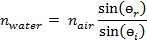
Snell’s Law dictates the angle at which light will be bent when crossing the boundary between two media. The measured incident and refracted angles at the water-air interface are given in Table 1. Below, a sample calculation giving the index of refraction for water using Snell’s Law is shown for an angle of incidence equal to 30.1° as the light goes from the water to air:

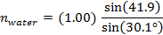
 1.33
1.33
The calculation can be repeated for the various angles in Table 1, and the average of the measurements will provide an even better measurement of the index of refraction than any of the individual measurements will provide.
Table 1: Results.
| Interface | өi | өr | nwater |
| Water → Air | 10.0 | 13.5 | 1.34 |
| Water → Air | 19.8 | 26.6 | 1.32 |
| Water → Air | 30.1 | 41.9 | 1.33 |
| Air → Water | 20.1 | 15.1 | 1.32 |
| Air → Water | 44.9 | 32.0 | 1.33 |
| Air → Water | 75.2 | 46.7 | 1.33 |
The critical angle for total internal reflection occurs when the refraction angle is equal to 90°. For the water-air interface, Snell’s Law predicts that the critical angle of incidence is 48.8°.
It is worthwhile to note that the refracted beam could still be observed at an angle greater than 48.8° when looking at the interface at which the light beam went from air into the water. It is only at the boundary at which the beam went from the water to the air that the beam was internally reflected at angles greater than 48.8°. Total internal reflection can only occur when light goes from a medium with a high index of refraction to a medium with a lower index of refraction.
For the lens part of the experiment, when the object was placed at about o = 11.02 cm, the image came into focus at about 9.21 cm. The thin lens equation then reveals the focal length of the convex lens to be about 5.02 cm.
Applications and Summary
This lab explores the physics of refraction and lenses. Snell’s Law was used to measure the index of refraction for water using measurements of incident and refracted angles. The phenomenon of total internal reflection at the water-air interface was also observed. It was shown that concave lenses can focus light and also create virtual images, allowing them to serve as magnification devices.
The human eye sees by focusing light onto the retina, and poor vision can result if the light focuses in front of or behind the retina. Eyeglasses help to correct poor vision by properly refocusing the light onto the retina. Cameras use a lens to focus light onto a sensor the same way that eyes focus light onto the retina. Magnifying glasses are simply convex lenses that create enlarged, virtual images of objects. Optical microscopes use multiple lenses to immensely magnify small objects, such as cells. Similarly, there is a type of telescope called a refractor that uses lenses to capture the light from stars, galaxies, and other astrophysical objects. Total internal reflection is used most often in the form of optical fibers, which are used for data transmission and as fiberscopes.
Transcript
Light reflects and travels at different speeds and direction, or refracts, depending on the material through which it is propagating, causing many interesting optical phenomena.
When a ray of light strikes the surface of a glass block, a part of it changes direction at the interface to return into the medium from which it originated; this is reflection. And the rest of the light changes its direction at the interface and travels through the block of glass to conserve energy and momentum; this is refraction.
Lenses found in optical systems like microscopes make use of reflection and refraction to create images that can be perceived by the human eye.
Here, we will first discuss the principles and parameters of reflection and refraction. Then we will demonstrate these phenomena in a system where air and water are the two media. Next, we will study the ways in which lenses create images, followed by a few applications in the field of optics.
To understand the principles and parameters of reflection and refraction, let us pick two media – water and air.
The first key parameter to note is “refractive index”, ‘n’ – a characteristic of the medium through which light travels. It is defined as the ratio between the speed of light in vacuum, ‘c’, to the speed of light in the medium, ‘v’. As the n of air is lower than water, light travels more slowly through water as compared to air.
Let us now assume that the two media, water and air, are in contact with each other along an interface.
Now when light travels from water to air and hits the interface, some of it is reflected at the interface, and the remaining is refracted or bent by an angle that depends on the refractive indices of the two media. Both reflection and refraction are also dependent on another parameter – angle of incidence, or θi.
This is the angle between the incident light and the normal to the air-water interface inside the first medium, water. The ‘angle of reflection’ is measured between the reflected light and the same normal inside the first medium, water, and is equal to the angle of incidence. Whereas the ‘angle of refraction’, or θr is the angle between the refracted light and the normal to the air-water interface in the second medium, air.
The angle of refraction is thus dependent on the angle of incidence and the refractive indices of the two media. The law of refraction or Snell’s Law provides a relationship between all of these parameters.
Now, if the angle of incidence is slowly increased, at one point the light would appear along the water-air interface, and the angle of refraction will equal 90 degrees. This incident angle is called the ‘critical angle’. Note that it can only happen if the refractive index of the first medium is greater than the second one.
Under this same condition, if the angle of incidence is increased further, then the light beam is refracted so sharply that it is actually completely reflected back into the first medium from which the light originated. This phenomenon is called Total Internal Reflection.
Having reviewed the parameters that affect reflection and refraction, let’s see how to perform an experiment in a physics lab that validates these principles. Gather all the necessary materials and equipment including a specialized refraction tank with a light beam.
Fill one half of the refraction tank with water. Turn ON the light beam and direct the beam into half of the tank filled with water.
Using a protractor, measure the light beam’s angle of incidence or the angle measured in the water between the light beam and the normal to the air-water interface. Also, measure the angle of refraction or the angle measured in air between the light beam and the normal to the air-water interface
Now, as the incidence angle is increased, a point is reached at which the light beam appears along the air-water interface. Make a note of this incidence angle, as it is the critical angle for total internal reflection.
Next, continue to increase the angle of incidence by rotating the light source counter-clockwise. The refracted beam now gets completely reflected into the water demonstrating Total Internal Reflection.
Subsequently, move the light source so that the beam enters the air-half of the tank first before travelling into the water. Repeat the protocol for the new light beam path for various angles of incidence and record the corresponding angle of refraction.
Now let’s talk about lenses, which take advantage of reflection and refraction of light to create real and virtual images of objects. All lenses, whether convex or concave, have a focal length ‘f’, which is the distance from the lens at which light rays originating from infinitely far away will be focused after passing through the lens. For convex lenses f is positive and for concave lenses f is negative.
When an object is placed in front of a lens, it creates an image. The ‘Thin Lens Equation’, provides a mathematical relationship between the focal length ‘f’, the distance between the object and the lens, ‘o’, and the distance between the lens and the image, ‘i’.
It is this mathematical image distance ‘i’ that tells us whether an image formed by the lens is real or virtual. If the mathematically calculated ‘i’ is positive then the image formed will be real, and if it is negative the image will be virtual.
For a convex lens, when the object distance ‘o’ is greater than the focal length ‘f’, the mathematically calculated image distance ‘i’ will be positive and a real image is formed. This is due to the physical convergence of light rays that come from the object, like the image captured by a camera or a microscope.
However, when the object distance ‘o’ is less than the focal length ‘f’, the mathematically calculated image distance ‘i’ is negative and a virtual image is formed. This is because the light rays appear to converge but actually physically diverge, and our eyes construct a point of origin for them. This is observed in the case of a magnifying glass, where a magnified virtual image is formed.
For concave lenses, the light rays that come from the object pass through the lens and always diverge. Thus, the calculated ‘i’ is always negative and the image created is always virtual.
In this section, we will validate the formation of real and virtual images using simple convex and concave lenses. Gather the required materials, namely a convex lens, a concave lens, a sheet of white paper, a small distinctive object, and a clamp to hold the paper vertically
First, place the convex lens between the object and the piece of paper. Make sure that they are all in line and at the same height.
Move the object and paper around until a sharp image of the object appears on the paper. This image seen on the paper is a real image, as it can be captured on a screen.
Now measure the distance from the lens to the object and from the lens to the paper. Use the thin lens equation to determine the focal length of the lens.
Next, place the paper aside and move the object closer to the lens until the distance between the lens and the object is less than the focal length of the lens. Look through the lens and observe the image.
Replace the convex lens with a concave lens. Look through the concave lens and observe the demagnified virtual image.
Now that we have completed the experimental protocol, let’s review how to analyze the data obtained. In the first experiment, we measured the angle of incidence and the angle of refraction at the water-air interface.
By using the Snell’s law and substituting the values for these angles into the equation, along with the refractive index of air, we can calculate the refractive index of water, which comes out to be 1.33.
This calculation can then be repeated for the various incident and refraction angles. The average of all the calculated refractive indices will provide a more accurate measurement of the index of refraction of water.
We can also calculate the critical angle for total internal reflection using Snell’s law. This is the incidence angle when the refraction angle equals 90 degrees. Rearrange this equation to solve for critical angle.
Using the previously calculated average for the refractive index of water, Snell’s law predicts that the critical angle of incidence is 48.8 degrees. This is very close to the angle measured experimentally, thus verifying Snell’s law.
When the light beam is projected from air to water, total internal reflection does not occur even at angles greater than 48.8 degrees as light is now traveling from a medium of lower index to higher.
In the experiment with the lenses, the thin lens equation reveals that for an object distance of 11.02 centimeters from the lens and an image distance of about 9.21 centimeters, the focal length of the lens is about 5.02 centimeters.
In the case where the object is observed through a convex lens, at a distance less than its focal length, a magnified version of the object is observed. This is a virtual image, as this image cannot be captured on a screen. Similarly, when using the concave lens, a demagnified virtual image of the object is observed.
Optics, specifically optical lenses, is used in every walk of life from photography to medical imaging to the human eye.
Optical fibers are used for data transmission in many current day applications, like transmission of telephone signals. These fibers consist of a core, cladding, and a protective outer coating or buffer, and other strengthening layers.
The cladding guides the data in the form of light pulses along the core using the method of total internal reflection. This property of data transmission enables fiber optic cameras used by doctors to view confined spaces in human body.
Microscopy is the field of using microscopes to view objects that are not visible to the naked eye. Optical or light microscopy involves passing visible light, which is refracted through or reflected from the sample, through a single or multiple lenses to allow a magnified view of the sample. The resulting image can be detected directly by the eye, or captured digitally.
You’ve just watched JoVE’s introduction to reflection and refraction. You should now understand the principles of refraction, Snell’s law, and total internal reflection and also the theory behind lenses and how they create images. As always, thanks for watching!