We have devised a method for low-cost and rapid prototyping of liquid elastomer rubber injection molded devices by using fused deposition modeling 3D printers for mold design and a modified desiccator as a liquid injection system.
Biologically inert elastomers such as silicone are favorable materials for medical device fabrication, but forming and curing these elastomers using traditional liquid injection molding processes can be an expensive process due to tooling and equipment costs. As a result, it has traditionally been impractical to use liquid injection molding for low-cost, rapid prototyping applications. We have devised a method for rapid and low-cost production of liquid elastomer injection molded devices that utilizes fused deposition modeling 3D printers for mold design and a modified desiccator as an injection system. Low costs and rapid turnaround time in this technique lower the barrier to iteratively designing and prototyping complex elastomer devices. Furthermore, CAD models developed in this process can be later adapted for metal mold tooling design, enabling an easy transition to a traditional injection molding process. We have used this technique to manufacture intravaginal probes involving complex geometries, as well as overmolding over metal parts, using tools commonly available within an academic research laboratory. However, this technique can be easily adapted to create liquid injection molded devices for many other applications.
Liquid injection molding (LIM) (also known as reaction injection molding) is often used to manufacture elastomeric devices from thermosetting elastomers, but high tooling and equipment costs require a great deal of up-front capital investment1. Furthermore, LIM can be technically challenging and expensive to implement in cases with complex geometry and requirements for overmolding. As a result, it is typically impractical to use traditional LIM in ultra-low volumes or with early-stage device designs that often incur iterative revisions.
The typical procedure for injection molding elastomeric materials involves injecting liquid monomers at pressures around 150 psi into a mold using specialized molding machinery2. Temperatures and pressures are controlled to ensure laminar flow and prevent air being trapped in the mold3. Raw materials are typically two-part cure systems, such as platinum cure silicone, that are kept in separate and temperature controlled chambers prior to injection. Both components of the raw material are pumped into a high-pressure mixing chamber that subsequently feeds into the mold cavity. Curing is achieved by the presence of a catalyst as well as temperatures around 150-200 °C4. Molds are typically machined from steel or aluminum to precise tolerances to create a good seal around parting edges3,5. Unfortunately, this process is generally more suited to larger scale manufacturing given high mold tooling costs as well as the requirement for specialized injection and feedback control systems.
For rapid prototyping of polyurethane (PU) parts, it is possible to use stereolithography (SLA) to create a mold master and produce a silicone rubber mold6,7. However, this technique is not suitable for overmolding since it is difficult to achieve precise alignment of overmolded components, as the silicone is, by design, not a rigid structure. Furthermore, production of devices with complex geometries, such as invaginations or hollowed out sections, is difficult or impossible. The requirement for complex or precise mold parting lines and rigid thin elements are more often than not, incompatible with the liquid rubber molding process.
The aforementioned production-scale or late-stage prototyping processes are often impractical for early-stage medical device development in which a few devices need to be produced for proof-of-concept and feasibility in human studies, as is often the case in academic laboratory and start-up company environments. The lack of alternatives often means that even early-stage development would incur high costs, requiring many device developers to limit device functionality or put development on hold while additional funds are raised. This contributes to a dramatic slowing of the development process since a large fraction of medical devices require implementation of complex features. It is also difficult to fund the costly development of such devices since proof-of-concept data is often not yet established. We encountered this roadblock in a recent project within this lab, which involved the development of a silicone intravaginal probe with overmolded electrical and optical sensors that required a cup-like tip to conform to specified cervical geometries. The process described in this article documents our attempt to circumvent this vicious cycle and rapidly reach proof-of-concept for LIM medical devices.
The technique shown in Figure 1 deconstructs the LIM process into 5 main activities: (1) mold design & production, (2) mold assembly (3) elastomer mixing, (4) elastomer injection, and (5) elastomer curing & demolding.
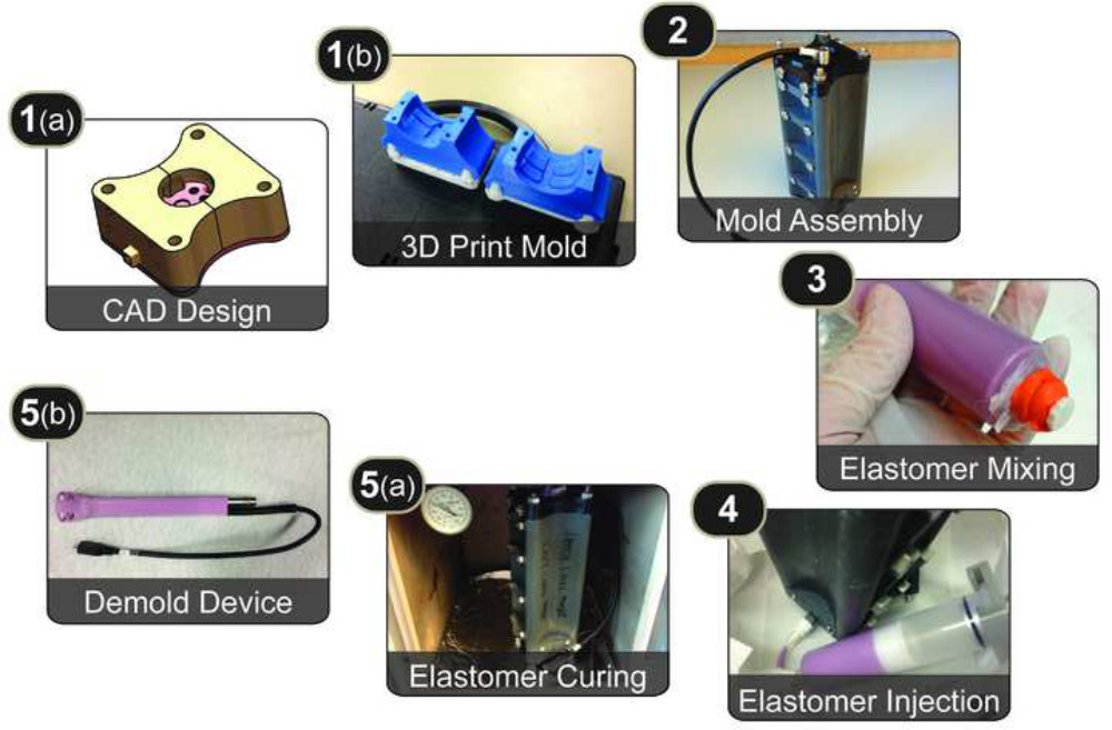
Figure 1. Protocol Overview. Overview of the protocol, which involves: (1a) creating a mold using computer-aided design tools, (1b) 3D printing the mold pieces, (2) assembling the mold pieces using threaded rods and screws, (3) mixing liquid elastomer and loading it in a syringe, (4) injecting the liquid elastomer into the mold using a modified desiccator, (5a) curing the elastomer in a temperature-controlled oven, and (5b) demolding the cured elastomer device from the mold pieces.
Mold design involves development of a mold master in computer-aided design (CAD) software, subtraction of the mold master from a solid block and definition of mold parting lines. Mold pieces are created and then assembled using screws, rods, and nuts with overmolded components positioned in the mold cavity. Elastomer mixing involves combining parts A and B of raw material and degassing to remove potential void spaces in the material. Next, elastomer injection involves pressure-driven filling of the mold cavity, followed by elastomer curing in a temperature-controlled oven to ensure chemical crosslinking of the polymer chains.
Breaking down the injection molding process into these steps enables us to forego traditional LIM equipment in favor of low cost alternatives. For example, instead of machining a metal mold or casting a silicone rubber mold from a mold master, the molds created from the protocol described in this manuscript were created from acrylonitrile butadiene styrene (ABS) plastic using a fused-deposition modeling (FDM) 3D printer8,9. Compared to building metal molds or SLA molds, FDM is generally a cheaper and faster process. Fairly complex molds can be printed quickly on an in-house 3D printer, or cheaply produced by one of the many contract 3D printing services available. For example, a complex eight-piece 3D printed mold was used to cast the demonstrated intravaginal probe in the representative results section and shown in Figures 14 and 15. All parts for this mold can be printed in approximately 1.5 days on an in-house 3D printer. Turnaround times for simpler molds can be a few hours. The overall length of time necessary to prototype a device using FDM 3D printers to create molds is similar to the time required to cast a mold out of silicone rubber and create a polyurethane prototype. However, using FDM 3D printers to create molds allows for several things that cannot easily be accomplished using a silicone mold: (1) many thermosetting elastomers can be used provided the 3D-printed mold can tolerate the required curing temperatures, (2) complex geometries can be created with the use of many different mold pieces and parting lines, and (3) use of rigid mold pieces allows precise and reproducible alignment of overmolded components within the mold cavity.
Instead of using a traditional LIM machine, which combines mixing, injection, and curing, it is possible to use a laboratory mixer to ensure homogenous mixing, a modified desiccator for injection, and a standard temperature-controlled oven for curing. The injection system was created using off-the-shelf components and involves the addition of a positive pressure supply line into the desiccator that connects to a syringe filled with mixed elastomer. Chamber pressurization in bench top desiccators is typically controlled by a three-way valve between the chambers, a vacuum supply line, and the atmosphere. The modified desiccator adds a positive pressure supply line feeding to the back of a syringe plunger. This enables the creation of a 40-50 psi pressure differential that is sufficient for liquid material injection into the mold cavity.
This technique allowed us to produce silicone intravaginal probes with overmolded electrical and optical sensors to collect proof-of-concept data for a Phase I clinical trial. Silicone was selected because of the need for biological inertness as well as the ability to sterilize with a variety of methods10,11. Furthermore, the device required a complex and unconventional cup-like geometry at the tip of the probe where sensors are located to interface with the cervix. Without the use of the described technique, it would have been a much more costly and lengthy process to produce these devices. This adaptation of the LIM process reduces cost and equipment requirements when compared to the traditional LIM process, making it practical to adopt a rapid and iterative approach to designing elastomeric devices.
This protocol describes the use of specific terminology and features in the SolidWorks software used for Mold Design and Production steps, though other software packages may also be used to accomplish the same result.
1. Mold Design and Production
2. Mold Assembly
3. Injection Chamber
4. Elastomer Mixing
5. Elastomer Injection
6. Elastomer Curing & Demolding
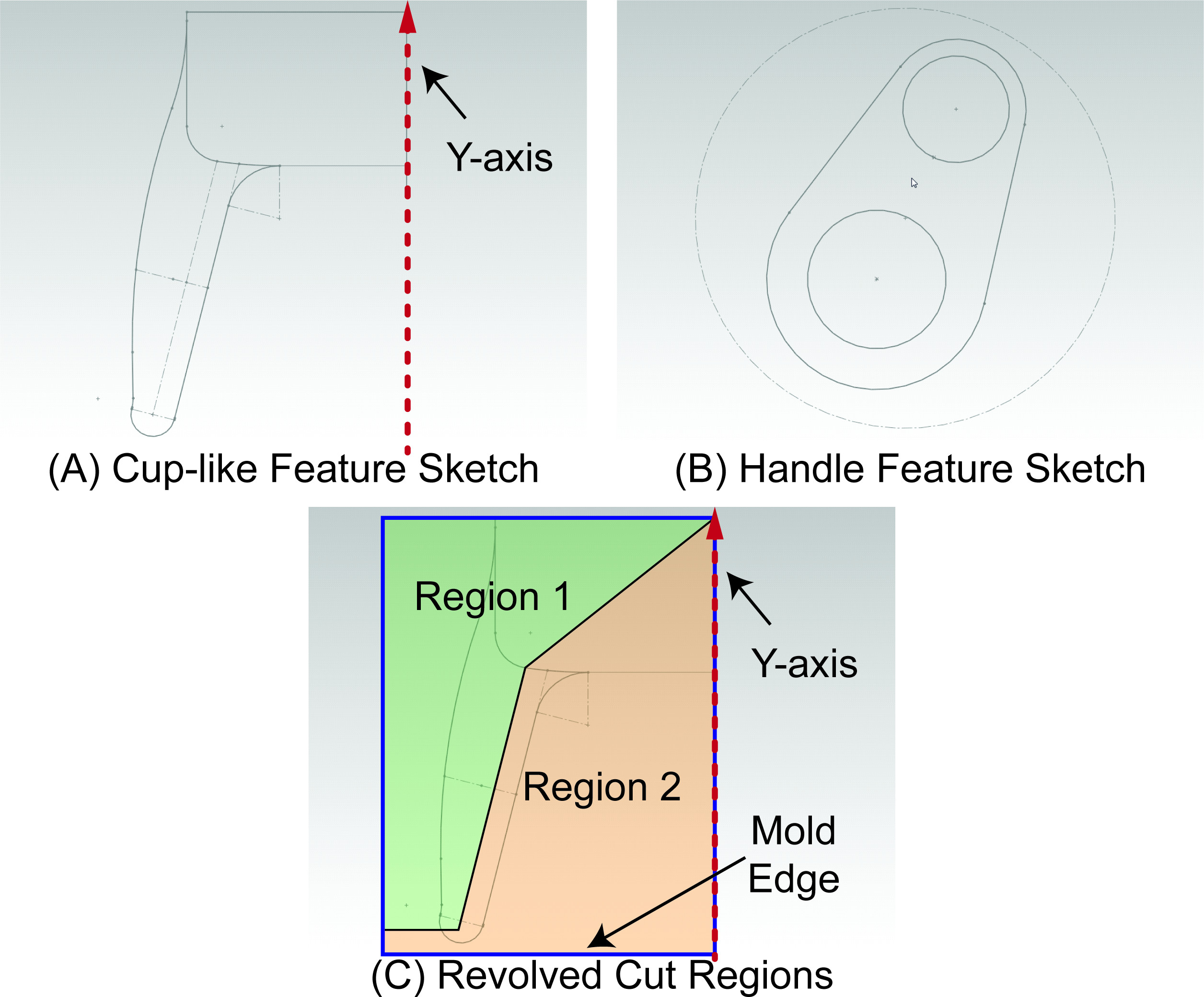
Figure 2. 2D CAD Sketches. A) 2D Sketch that can be radially revolved about the Y-axis to produce a cup-like feature similar to the one on the intravaginal probe device. B) Teardrop-shaped 2D sketch that can be extruded out of the plane into a prism-like structure that forms the handle of the intravaginal probe device. C) An example sketch that creates two regions in the radial cross section of the cup-like feature region of the mold. Revolved cuts selectively in Region 1 or Region 2 around the Y-axis will yield different mold pieces.
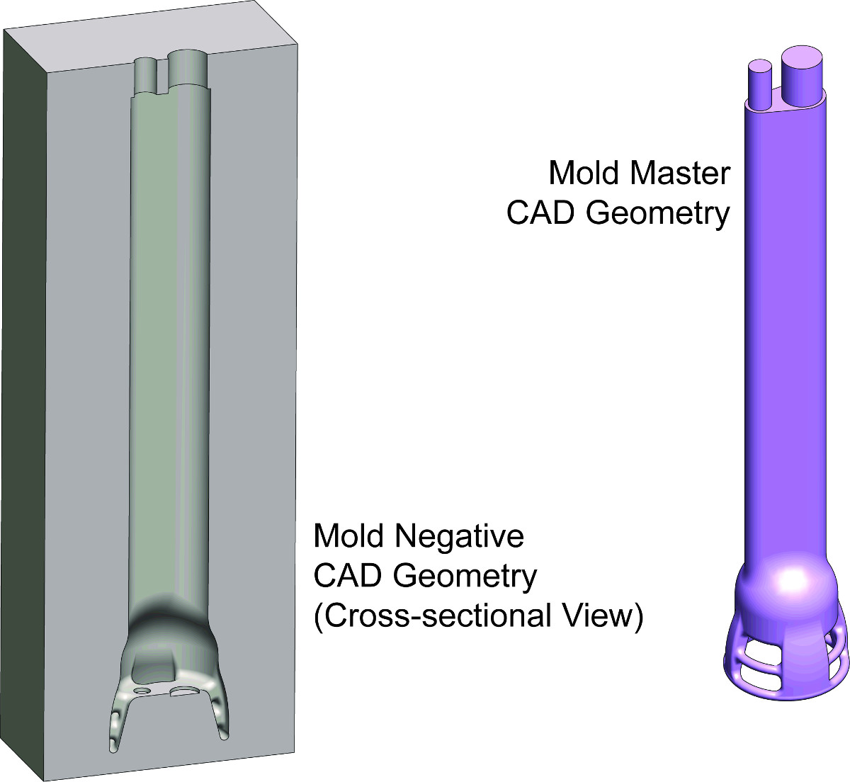
Figure 3. Creating the Mold in CAD. CAD drawings of the mold master (right) and mold negative (left) for an intravaginal probe device is depicted. The mold negative is created by subtracting the mold master geometry from a rectangular prism and will eventually be partitioned into two or more pieces and become a functional mold.
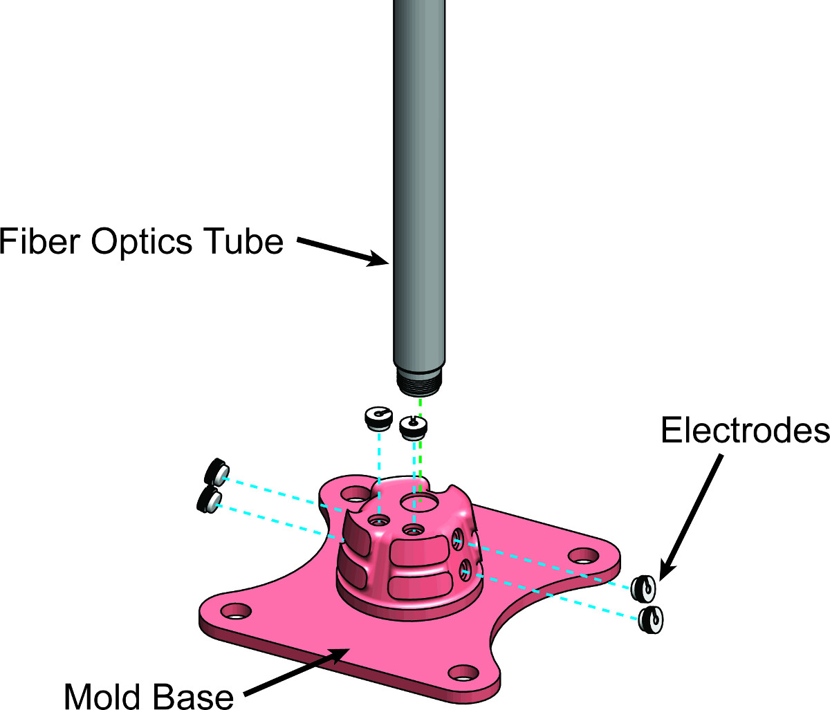
Figure 4. Designing Alignment Guides in the Mold. Exploded CAD drawing of the mold base, fiber optics tube, and electrode components. The fiber optics tube and electrodes must be precisely positioned and overmolded to produce an intravaginal probe. Alignment guides are designed into the mold base to allow these components to stay in place while liquid elastomer is being injected into the mold cavity.
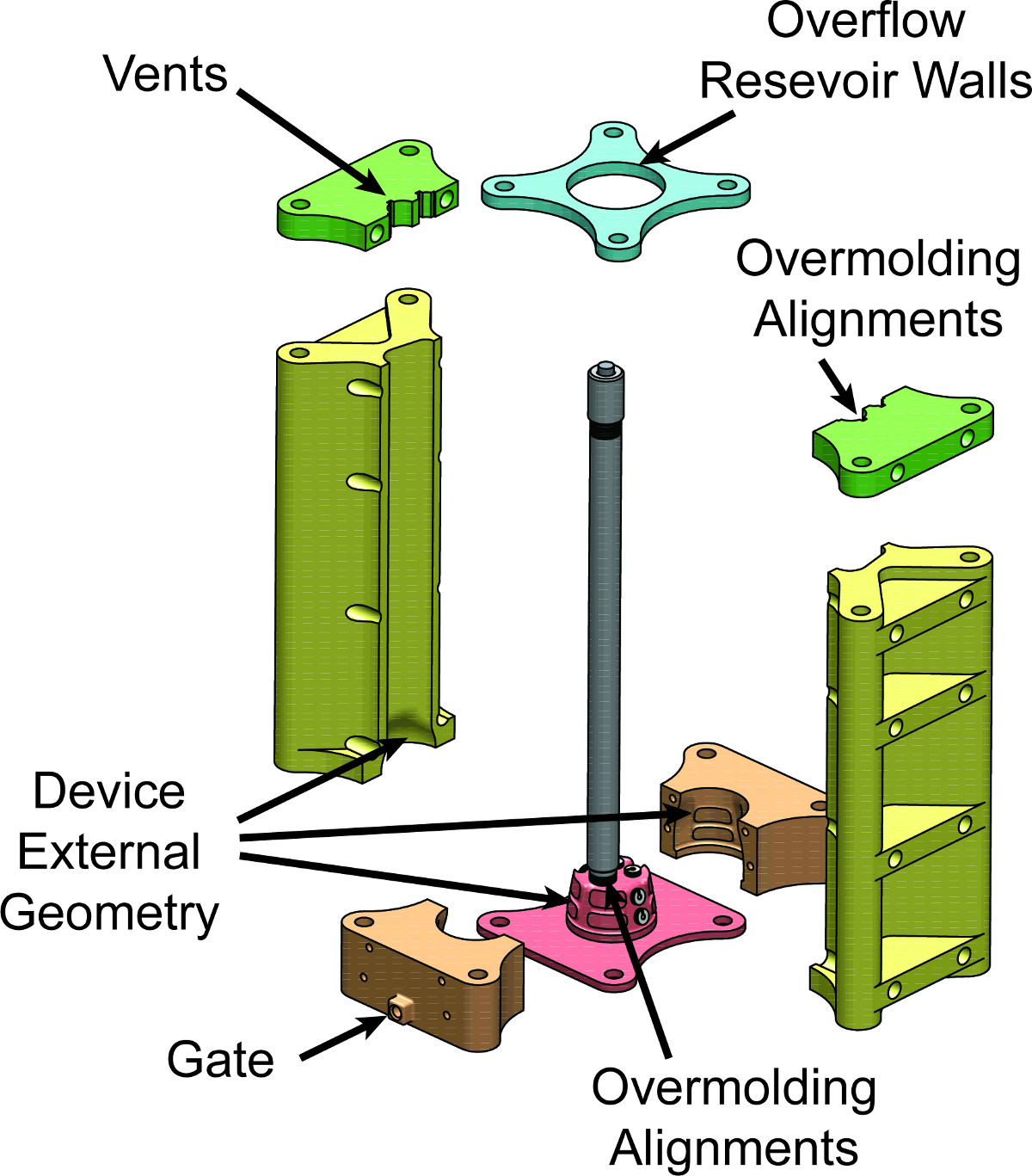
Figure 5. Mold: Exploded View. Exploded CAD drawing of the finished mold assembly for the intravaginal probe device. The geometry of the mold cavity not only specifies the external geometries of the final intravaginal probe device, but also provides anchoring and positioning points for components to be overmolded. Specifically, the mold base geometry and the upper left and upper right pieces align the fiber optics tube, and the mold base provides insets for aligning the electrodes on the final device.
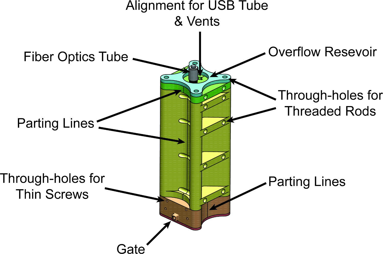
Figure 6. Mold: Assembled View. CAD drawing of the finished mold assembly for the intravaginal probe device. Liquid elastomer will be injected into the gate and fill the mold cavity before flowing into the overflow reservoir at the top. Vents running from the mold cavity to the overflow reservoir are carefully designed into the alignment pieces of the mold at the top.
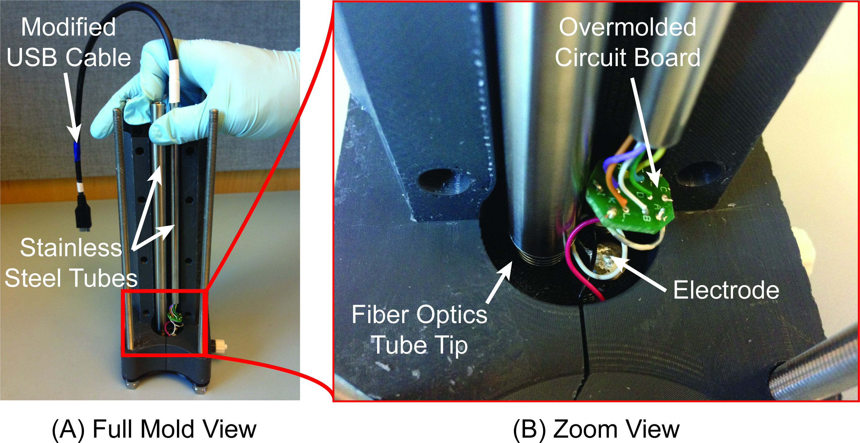
Figure 7. Alignment of Overmolded Components. A) Partially assembled mold depicting the alignment of two stainless steel tubes, a small printed circuit board, and six electrodes in the mold cavity. Positioning mold pieces at the top of the mold along with invaginations in the mold base physically constrain movement of all components during elastomer injection. B) Zoom view of the bottom of aligning components near the mold base.
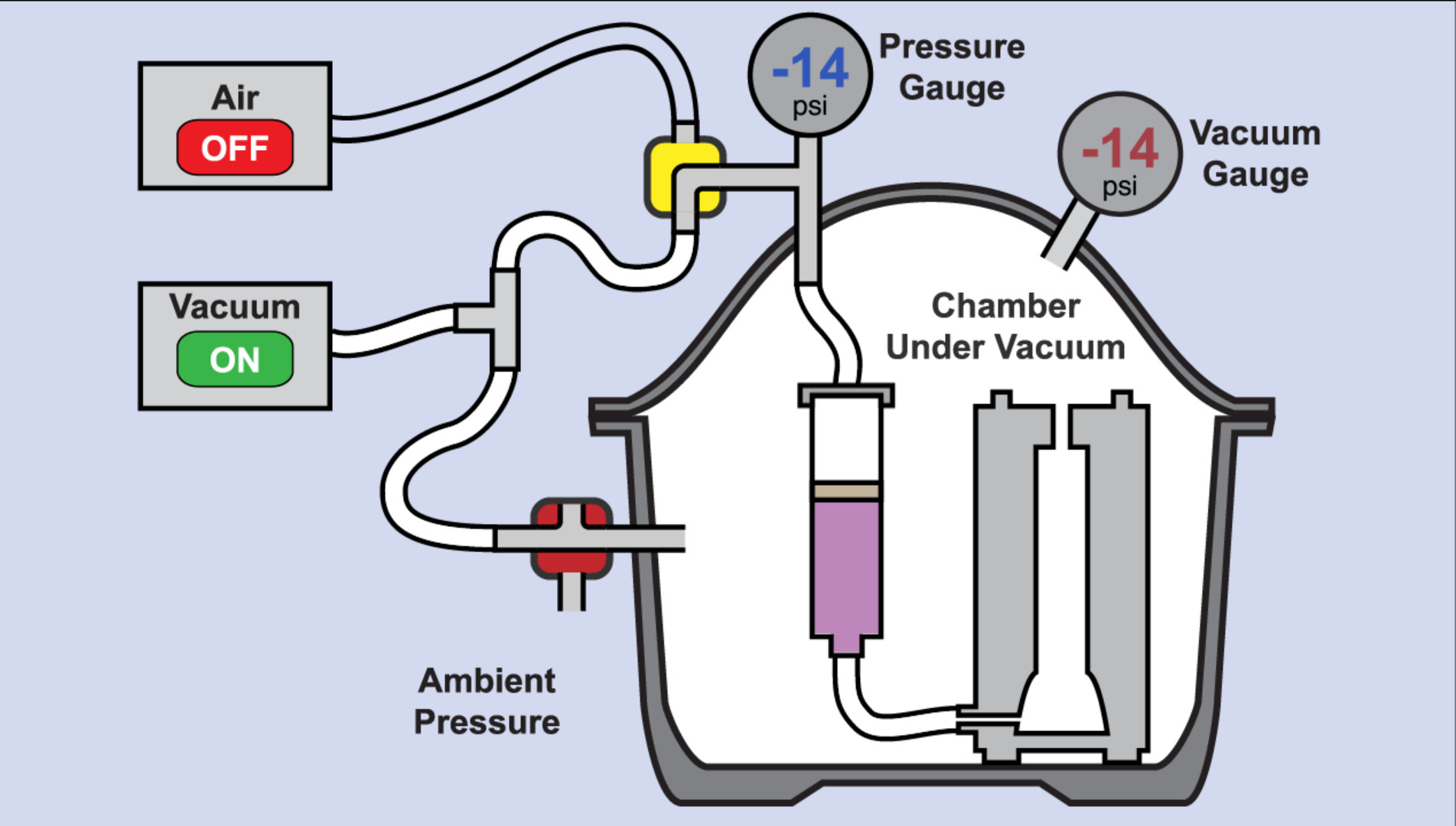
Figure 8. Elastomer Injection Process. Animation that first depicts modifications to a standard laboratory desiccator to create the injection chamber, and then depicts the manipulation of pressures to inject liquid elastomer from a syringe into a mold. Please click here to view this video.
Figure 9 is a schematic that describes how to modify the desiccator to create the completed injection chamber.
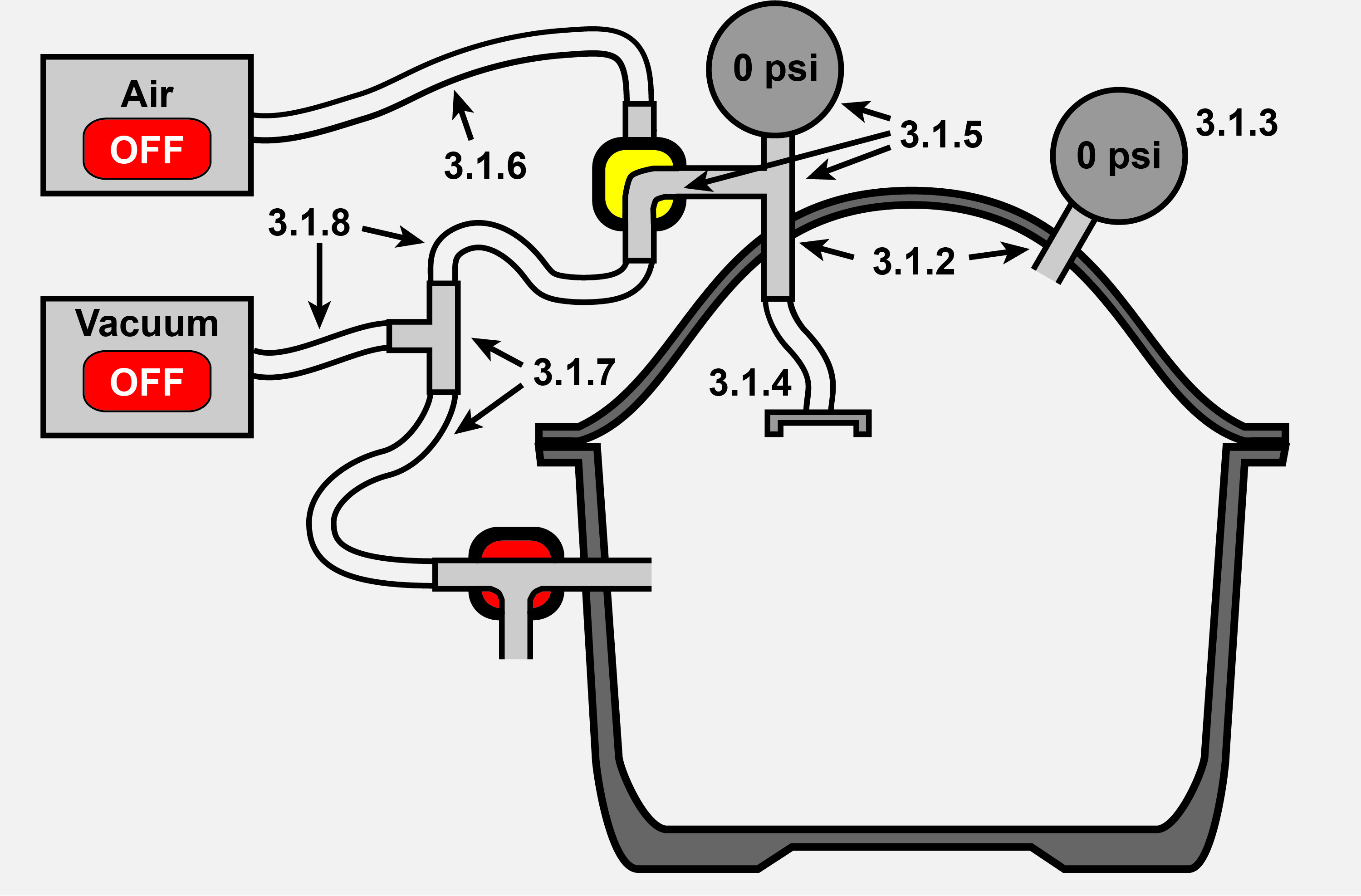
Figure 9. Creating the Injection Chamber. Injection Chamber after desiccator modification is completed. Corresponding steps in the procedure are labeled in the figure.
See Figure 10C & 10D for the injection chamber used to fabricate the intravaginal probe.
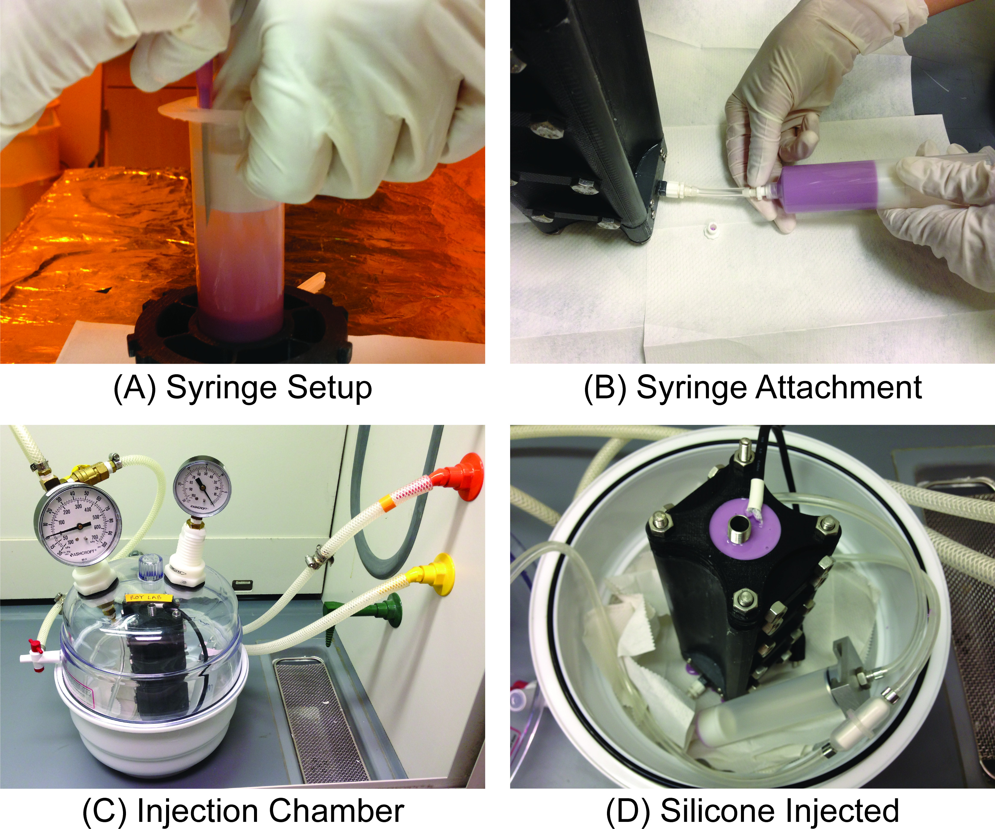
Figure 10. Elastomer Mixing and Injection. A) After the liquid elastomer is mixed and degassed, a syringe plunger is inserted into the syringe. Air between the plunger and the elastomer is removed with the aid of a syringe needle as the plunger is inserted. B) The syringe with elastomer is attached to the mold at the gate via luer-lock couplings. C) The injection chamber is a modified desiccator that can generate at least 40-50 psi of pressure across the syringe plunger with the aid of a vacuum and positive air pressure supply. D) Mold after injection of elastomer using the injection chamber.
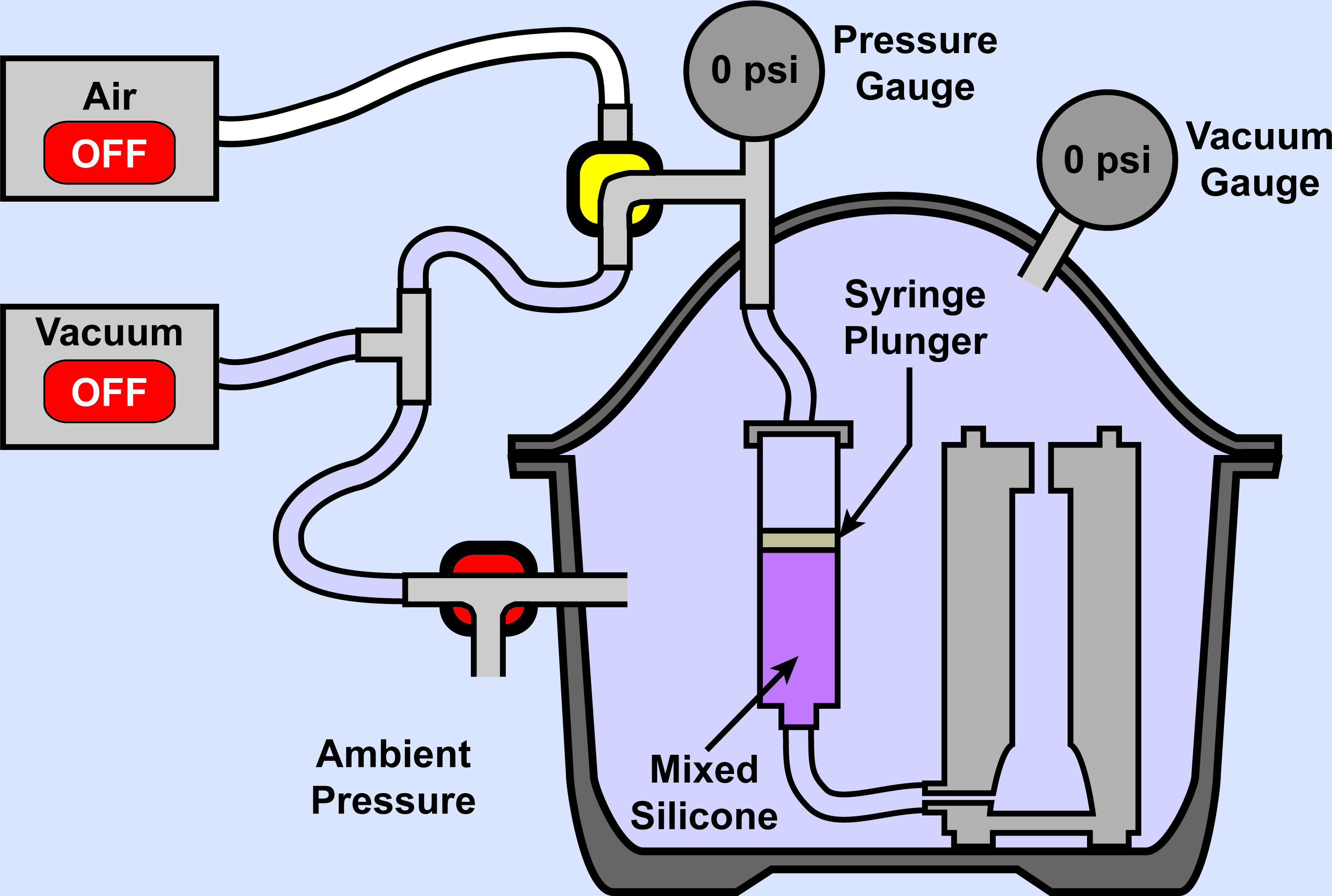
Figure 11. Elastomer Injection: Beginning. Injection chamber depicted at the start of the liquid rubber elastomer injection process. Both sides of the syringe plunger are exposed to ambient pressure.
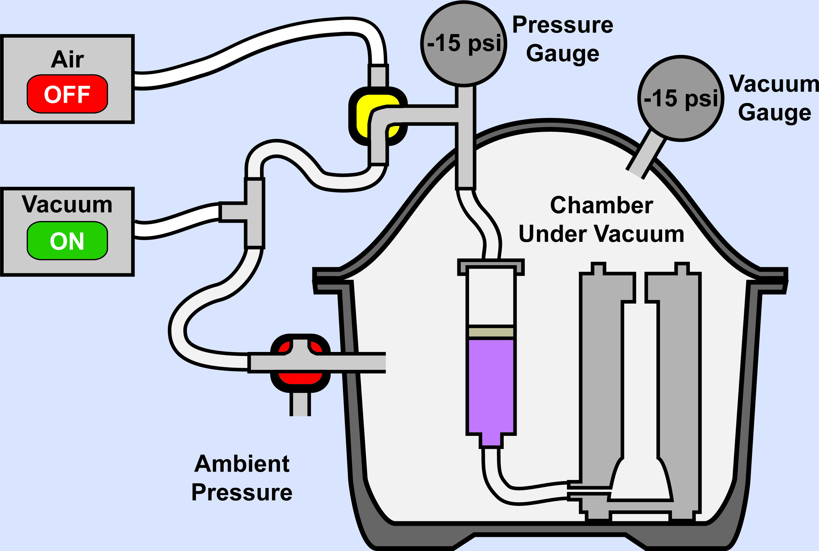
Figure 12. Elastomer Injection: Middle. Closing of 3-way valve near the bottom of the setup seals injection chamber and allows both sides of the syringe plunger to be pulled to a negative pressure.
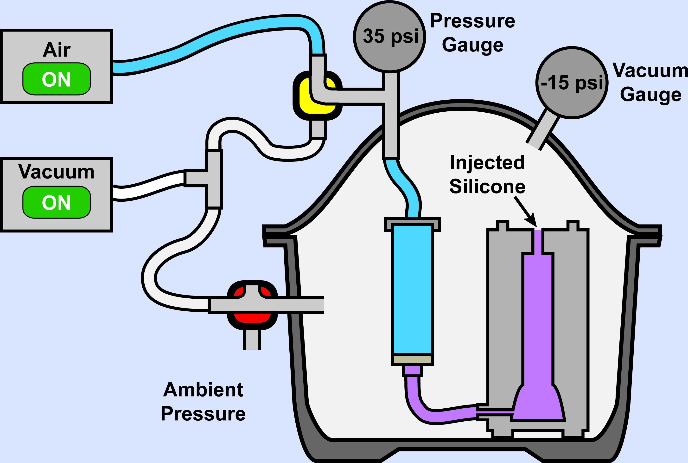
Figure 13. Elastomer Injection: End. Turning of the 2-way valve at the top of the setup allows application of positive air pressure behind the syringe plunger, generating at least 40-50 psi.
The mold and intravaginal probe in Figures 14 and 15 demonstrates representative results of the procedure presented in this article.
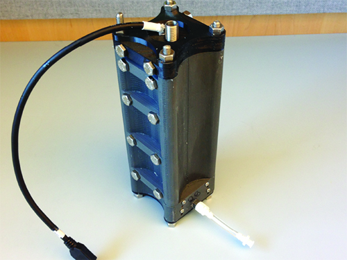
Figure 14. Fully Assembled Mold. Fully assembled mold for intravaginal probe device.
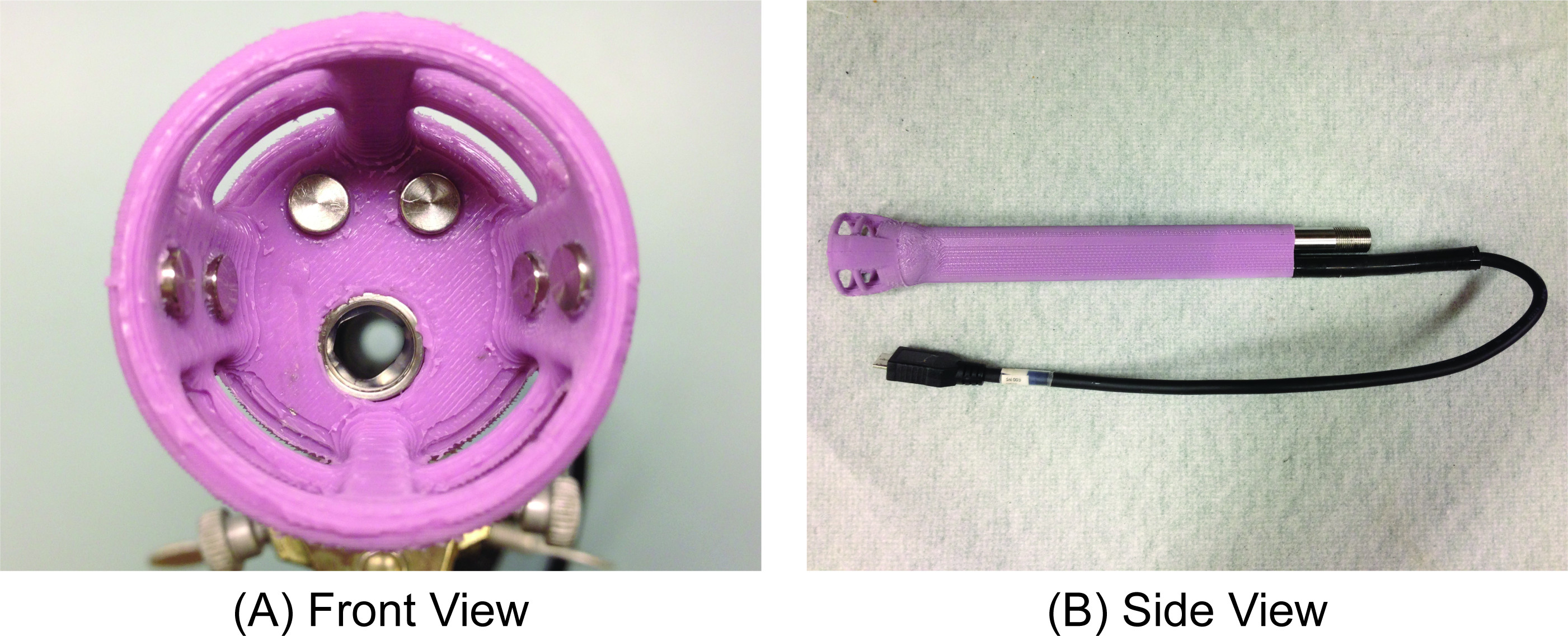
Figure 15. Intravaginal Probe Device. Final intravaginal probe device. A) Front view of the cup-like tip of the device. B) Side view of the same device. The cup-like structure consists of six overmolded titanium electrodes as well as a stainless steel tube that acts as a female receptacle for a fiber optic probe.
Specific use of this device is described in Etemadi et al12,13. The mold used to create the intravaginal probe was fabricated from ABS430 material using a Dimension uPrint Plus 3D printer. One mold for the intravaginal probe required approximately 1 reel of ABS430 material priced at $140 per reel. It took approximately 1.5 days to print all eight pieces of the mold.
A medical grade two-part platinum cure silicone designed for LIM applications (PN40029) was used in this application. Overmolded in the bulk silicone are custom stainless steel tubes, a modified USB cable, several wires, and titanium electrodes, which were kept in place during silicone injection via carefully designed alignment and positioning geometries in the mold. One of the tubes is exposed at the base of the cup-like structure on the intravaginal probe and has a glass window on the end of the tube to act as a female receptacle for a fiber optic bundle used for optical measurements. This is the sole external feature that was added after the silicone was cured and demolded using the documented process.
Specific results may vary depending on the desired geometry and whether or not overmolding is required. The intravaginal probe demonstrates that creation of complex geometries such as a thin cup-like structure is possible with FDM 3D printers, though simpler geometries would likely require fewer mold pieces, less mold material, and would be faster to 3D print. Use of higher resolution 3D printing technology such as SLA may be able to provide higher resolution, finer geometries, and superior surface finishes which may eliminate the need to manually finish molds. Using the technique described, overmolding of many different components may be accomplished as long as mold design is implemented carefully.
Of all the steps described, careful mold design is the most critical to success. The mold master should be created as a solid body with external geometries equal to the final device. These geometries should be adjusted to account for any material shrinkage due to the chosen elastomer as well as 3D printer resolution and tolerances. Placement of mold parting lines and through-holes for threaded rods and screws are dependent on one another. Adding parting lines increases the number of linear and rotational degrees of freedom of the mold assembly. Through-holes and threaded rods and screws act to constrain these same degrees of freedom. The mold must be designed such that it constrains all linear and rotational degrees of freedom when fully assembled, while enabling the removal of a fully cured elastomer device when the constraining threaded rods and screws are removed. If the cured elastomer is reasonably elastically deformable, parting lines can be defined such that features overhang one another slightly since the fully cured device can be pushed or pulled out of mold pieces. If overmolded components are desired, the mold design must also provide positioning features to constrain movement of overmolded components in a fully assembled mold. Mold parting lines should be carefully chosen to minimize the number of mold pieces that are necessary to produce the desired elastomer device. Minimizing the number of mold pieces and parting lines decreases the potential for flash formation and decreases the number of through-holes necessary for compressing the mold pieces during mold assembly. From our experience, an ABS mold lasts around 20 uses before the ABS plastic wears out, cracks, or crazes due to compressional stresses and heating cycles.
Once mold pieces have been printed using FDM 3D printers, several modifications can be made to the mold pieces. In some cases, mold pieces made from FDM 3D printers may have insufficient resolution to produce perfectly flush surfaces at the parting lines, resulting in a small gap that can lead to flash formation as well as leakage of liquid elastomer. If this occurs, use of a thin layer of RTV silicone at the parting lines of an assembled mold can prevent leakage of liquid elastomer through the mold parting lines. Alternatively, surface smoothing can be accomplished either by adding extra material to mold pieces (oversizing them) and sanding to final dimensions or by treating the ABS with acetone, which gradually dissolves the plastic. These methods can be carefully used to fine-tune mold geometries at the parting edges to reduce flash formation. However, one must be careful when dissolving mold surfaces, since doing so will chemically reduce the strength of plastic, making it easier for cracking and crazing. This can reduce the lifetime of the mold and also affect consistency of surface geometries between molds. Furthermore, it is difficult to control the uniformity of mold dissolution, which may cause slight variations in mold geometry. This may become an issue if multiple sets of molds are used to fabricate devices. To work around this problem, higher resolution 3D printing techniques can be used for mold production. Another benefit of utilizing a higher-resolution mold or acetone-treated mold is the added ease of separating the elastomer device from the ABS molder during demolding. Alternatively, mold releases can be used to coat the mold cavity to assist demolding. However, for the intravaginal probe demonstrated in this procedure, mold release was specifically avoided due to the potential risk of introducing mold release chemicals into the vaginal environment. Care should also be taken to ensure that selected mold material does not inhibit curing of the elastomer.
One challenge in overmolding components in silicone elastomer, such as the one used for the intravaginal probe, is that adhering silicone and metal is notoriously difficult. One requirement for the intravaginal probe was to allow small gaps at the material interfaces to occur if the silicone is elastically deformed. This reflects the desire to allow the cup-like structure on the intravaginal probe to flex and stretch like a sleeve around the cervix while still ensuring water tightness between both metal and silicone parts of the device. Water tightness was necessary due to human experiment guidelines for cleaning and sterilization of the device in hydrogen peroxide plasma. This requirement was met after demolding the devices by carefully applying a medical grade silicone to metal adhesive primer to the junction between the silicone device body and metal components and then applying room temperature cure (RTV) silicone to the metal-elastomer junctions. An additional method employed to improve adhesion between metal and silicone was to design all embedded metal components with circular fins. Upon injection, space between the fins is filled with liquid silicone, which then solidifies during curing. This design feature allows stresses to be transferred from the silicone body to metal components while reducing the tendency for gap formation between metal and silicone.
While there are many advantages associated with the use of ABS-based FDM 3D printers—namely rapid print speeds, low cost, and plethora of contract printing services that use the technology—these benefits must be carefully weighed with respect to the trade-offs being made. ABS-based 3D printers enables a rapid prototyping and iterative development approach while ABS itself is suitable for molding many elastomers because it is generally chemically inert14,15. However, ABS plastic has a heat deflection temperature of approximately 90-100 °C, which limits the maximum work temperature at approximately 70 °C16. This means that higher curing temperatures cannot be achieved using ABS molds. As a result, the cure time of the elastomer used for the intravaginal probe was increased from 3 min at 175 °C to 5 hr at 70 °C. If higher cure temperatures are desired, one may consider using other FDM materials such as polycarbonate. Use of SLA-based 3D printing enables the finest mold resolution possible and provides a wide selection of resin materials. However, continued advancement in FDM technology is closing the resolution gap between the two techniques. While the FDM-based molds used in creating the intravaginal probe had a layer resolution of 254 μm, newer FDM machines can achieve 100 μm resolutions and below. SLA-based 3D printing is generally more expensive and more time intensive than FDM-based 3D printing, and much fewer facilities possess in-house SLA equipment. These factors make FDM 3D printers more suitable for low cost rapid iterative development. In fact, SLA is commonly used for prototyping and low-volume runs of polyurethane devices by printing a mold master and casting a silicone mold around the mold master to create the mold for polyurethane injection. The benefit of using silicone as a mold material is that it is a thermosetting polymer and will not melt at higher curing temperatures. However, it is difficult or impossible to partition the silicone mold into many pieces to generate complex molds such as the intravaginal probe device; furthermore, alignments for overmolding may be similarly challenging. The result is that silicone molds produced with this method are generally two-piece molds and require traditional LIM equipment for injection of polymer into the mold cavity. Thus, while this method is not as expensive as traditional LIM injection, the total cost of prototyping using this method is still rather costly and is more time intensive than the described protocol for using FDM 3D printers and a modified desiccator for elastomer injection. Other benefits of the proposed methods include the ability to directly print mold pieces without first creating a physical mold master, as well as the fact that this technique does not require investment in costly SLA or LIM equipment.
The proposed method enables rapid prototyping of elastomer devices with complex geometries and requirements, which is a hallmark of fields such as medical devices. The lack of standard or documented methods to rapidly iterate elastomer devices has contributed to slow and costly development of medical devices. The inherent flexibility in the process described in this manuscript allows for almost any geometry to be built and overmolding requirement to be met. It can be used to rapidly and cheaply iterate device prototypes early in the medical device development process. This is especially useful in resource-limited environments such as academic laboratories or start-up environments where 3D printers are increasingly prevalent but LIM equipment is rare. Additionally, CAD models produced in this process are transferable to future manufacturing processes and can be used to facilitate production of traditional metal molds used for LIM. While this technique was demonstrated for medical device development with the intravaginal probe device, the protocol can easily be adapted for other fields and applications in which low-cost, low-volume, and rapid iterative development of elastomer-based devices are desired.
The authors have nothing to disclose.
The authors thank Sungwon Lim for intellectual contributions to device and mold design as well as Jambu Jambulingam and Rebecca Grossman-Kahn for creating intravaginal silicone probes using this process. This work is supported by the Bill and Melinda Gates Foundation, the Vodafone Americas Foundation, and the FDA (2P50FD003793).
ABS Model Material | Stratasys | P430 | Model Material for uPrint Plus SE (Step: Mold Design & Production) |
Soluble Support Material | Stratasys | SR-30 | Support Material for uPrint Plus SE (Step: Mold Design & Production) |
Underwater Silicone Sealant, 2.8 Oz Tube, Clear | McMaster-Carr Supply Company | 7327A21 | Silicone RTV for sealing gaps at mold parting lines (Step: Mold Assembly) |
Tubing, 1/8" ID, 1/4" OD, 1/16" Wall Thickness, Ultra-chemical-resistant Tygon PVC, Clear | McMaster-Carr Supply Company | 5046K11 | Forms runner/sprue adapter between mold and syringe with elastomer (Step: Elastomer Mixing) |
Coupling, Adapter, Straight, Male Quick-turn (Luer lock) X 1/8" Tube Barb, Nylon | McMaster-Carr Supply Company | 51525K123 | Connect runner/sprue between mold and syringe with elastomer (Step: Elastomer Mixing) |
Coupling, Adapter, Staight, Female Quick-turn (Luer lock) X 1/8" Tube Barb, Nylon | McMaster-Carr Supply Company | 51525K213 | Connect runner/sprue between mold and syringe with elastomer (Step: Elastomer Mixing) |
Cap, Female Quick-turn (Luer lock), Nylon | McMaster-Carr Supply Company | 51525K315 | Cap to prevent silicone from leaking out of mold after injection (Step: Elastomer Mixing) |
Liquid Silicone Rubber (LSR) 30 – 10:1, Implant Grade | Applied Silicone Corporation | PN40029 | Substitute with the elastomer of your choice. This is the one used for the intravaginal probe (Step: Elastomer Mixing) |
Syringes (BD), 1mL Slip-Tip, non-sterile clean, bulk | Cole-Parmer | WU-07945-00 | Syringes for transfering elastomer material (Step: Elastomer Mixing) |
Syringes (BD), 1mL Slip-Tip, non-sterile clean, bulk | Cole-Parmer | WU-07945-04 | Syringes for transfering elastomer material (Step: Elastomer Mixing) |
Syringe, 20mL, Open Bore, Solid Ring Plunger and Grip | Qosina Corporation | C1200 | Syringes for transfering elastomer material. Open bore is used for very viscous elastomers. (Step: Elastomer Mixing) |
Needle (BD), Non-sterile Clean with Shields, 18 gauge X 1.5" Lg., Stainless Steel, BD Bulk | Cole-Parmer | WU-07945-76 | Used for removing air column between syringe plunger and elastomer (Step: Elastomer Mixing) |
Plastic Cups, 12 Oz., Clear | Safeway | N/A | Used for mixing silicone in THINKY Mixer (Step: Elastomer Mixing) |
Polyethylene Bag, Open-Top, Flat, 5" Width X 6" Height, 2-MIL Thk. | McMaster-Carr Supply Company | 1928T68 | Used for mixing silicone in THINKY Mixer (Step: Elastomer Mixing) |
Rubber Band, Latex Free, Orange, Size 64, 3-1/2" L X 1/4" W | McMaster-Carr Supply Company | 12205T96 | Used for mixing silicone in THINKY Mixer (Step: Elastomer Mixing) |
Parafilm Wrap, 4"W | Cole-Parmer | EW-06720-40 | Used for mixing silicone in THINKY Mixer (Step: Elastomer Mixing) |
Syringe Barrels with Stoppers, Luer Lock, Air Operated, 50mL | EWD Solutions | JEN-JG50A-15 | Smaller syringes can be used if less elastomer is required, but make sure it is compatible with Air Operated Syringe Adapter in injection chamber (Step: Elastomer Mixing) |
Sealant Tape, Pipe Thread, 50'Lg X 1/4" W, .0028" Thk, 0.5 G/CC Specific Gravity | McMaster-Carr Supply Company | 4591K11 | Teflon Tape for air-tight seals around at threads (Step: Elastomer Injection) |
Scalpel Blades, Disposable, No. 22 | VWR | 21909-646 | Used for cutting tubing and demolding (Step: Curing & Demolding) |
Kimwipes | VWR | 21903-005 | (Step: Curing & Demolding) |
2-Propanol, J. T. Baker | VWR | JT9334-3 | (Step: Curing & Demolding) |
uPrint Plus SE 3D Printer | Stratasys | uPrint Plus SE | Other 3D printers can be used (Step: Mold Design & Production) |
Screw, Cap, Hex Head, 1/4"-28 , 2-1/2" Lg, 18-8 Stainless Steel | McMaster-Carr Supply Company | 92198A115 | Screws used with nuts to compress mold (Step: Mold Assembly) |
Nut, Hex, 1/4"-28, 7/16" Wd, 7/32" Height, 18-8 Stainless Steel | McMaster-Carr Supply Company | 91845A105 | Screws used with nuts to compress mold (Step: Mold Assembly) |
Stud, Fully Threaded, 1/4"-28, 1" Lg, 18-8 Stainless Steel | McMaster-Carr Supply Company | 95412A567 | Threaded-rods can be cut to desired length and are used with nutes to compress mold (Step: Mold Assembly) |
Planetary Centrifugal Mixer | THINKY USA Inc. | ARE-310 | Mixers are strongly recommended for fine mixing and to reduce degassing time, but hand mixing is fine (Step: Elastomer Mixing) |
Laboratory Weigh Scale | Mettler-Toledo International Inc. | EL602 | (Step: Elastomer Mixing) |
Desiccant Vacuum Canister, Reusable, 10-3/4" OD | McMaster-Carr Supply Company | 2204K7 | This desiccator is used for degassing the elastomer (Step: Elastomer Mixing) |
Custom 3D-Printed Mixer-to-Cup Adapter | N/A | N/A | Modeled in Solidworks CAD and 3D printed (Step: Elastomer Mixing) |
Tubing, Smooth Bore, 1/4" ID, 1/2" OD, 1/8" Wall Thickness, High Purity Tygon PVC, Clear | McMaster-Carr Supply Company | 5624K51 | Tubing outside of Desiccator (Step: Elastomer Injection) |
Tubing, Smooth Bore, 3/8" ID, 5/8" OD, 1/8" Wall Thickness, High Purity Tygon PVC, Clear | McMaster-Carr Supply Company | 5624K52 | Tubing to adapt to Air/Vacuum Supply (Step: Elastomer Injection) |
Coupling, Reducer, Straight, Vacuum Barb 3/8" Tube ID X Vacuum Barb 1/4" Tube ID, Brass | McMaster-Carr Supply Company | 44555K188 | Adapt Tubing outside Desiccator to Tubing leading to Air/Vacuum Supply (Step: Elastomer Injection) |
Clamp, Hose & Tube, Worm-Drive, for 7/32" to 5/8" OD tube, 5/16" Wd., 316 SS | McMaster-Carr Supply Company | 5011T141 | Used on tubing to create Air/Vacuum-tight seal at junctions (Step: Elastomer Injection) |
Clamp, Hose, Smooth-Band Worm-Drive, for 1/2" to 3/4" OD tube, 3/8" Wd., 304 SS | McMaster-Carr Supply Company | 5574K13 | Used on tubing to create Air/Vacuum-tight seal at junctions (Step: Elastomer Injection) |
Coupling, Tee, Vacuum Barb 1/4" Tube ID, Brass | McMaster-Carr Supply Company | 44555K138 | Tee Junction between Vacuum, Three-way T-valve on Desiccator, and Three-way L-valve (Step: Elastomer Injection) |
Coupling, Tee, 1/4 NPT Female X Female X Male, Brass | McMaster-Carr Supply Company | 50785K222 | Tee Junction between Pressure Gauge, Chamber, and Three-way L-valve (Step: Elastomer Injection) |
Valve, Ball, Straight, T-Handle, 1/4 NPT Female X Male, Brass | McMaster-Carr Supply Company | 4082T42 | Three-way L-valve (Step: Elastomer Injection) |
Coupling, Adapter, Straight, Vacuum Barb 1/4" ID Tube X 1/4 NPT Male, Brass | McMaster-Carr Supply Company | 44555K132 | Adapter for Three-way L-valve-to-Tubing (Step: Elastomer Injection) |
Saw, Hole, Bimetal. 1-3/8" OD, 1-1/2" Cutting Depth | McMaster-Carr Supply Company | 4066A25 | Used to cut holes in Desiccator for throughwall fittings (Step: Elastomer Injection) |
Arbor, 9/16" to 1-3/16" Saw, 1/4" Hex | McMaster-Carr Supply Company | 4066A76 | Used to cut holes in Desiccator for throughwall fittings (Step: Elastomer Injection) |
Arbor Adapter for 1-1/4" Thru 6" Dia Hole Saws | McMaster-Carr Supply Company | 4066A77 | Used to cut holes in Desiccator for throughwall fittings (Step: Elastomer Injection) |
Coupling, Straight, Through-Wall, 1/2 NPT Female, Polypropylene | McMaster-Carr Supply Company | 36895K141 | Throughwall fittings leading to Pressure/Vacuum Gauges (Step: Elastomer Injection) |
Coupling, Adapter, Straight, Reducing, Bushing, Hex, 1/2 NPT Male X 1/4 NPT Female, Brass | McMaster-Carr Supply Company | 4429K422 | Reducing tube diameter inside the Desiccator to adapt to Air-operated Syringe System (Step: Elastomer Injection) |
Coupling, Adapter, Straight, Reducing, Bushing, Hex, 1/4 NPT Male X 1/8 NPT Female, Brass | McMaster-Carr Supply Company | 4757T91 | Reducing tube diameter inside the Desiccator to adapt to Air-operated Syringe System (Step: Elastomer Injection) |
Coupling, Adapter, Straight, Vacuum Barb 1/4" ID Tube X 1/8 NPT Female, Brass | McMaster-Carr Supply Company | 44555K124 | Reducing tube diameter inside the Desiccator to adapt to Air-operated Syringe System (Step: Elastomer Injection) |
Syringe Adapters, Air Operated, 30/50mL | EWD Solutions | JEN-JG30A-X6 | Air operated syringe adapter on the inside of the Desiccator; must be compatible with syringes used to hold elastomer (Step: Elastomer Injection) |
Gauge, Dual-Scale Vacuum, 2-1/2" Dial, 1/4 NPT Male, Bottom Connector, 30" Hg-0, Steel Case | McMaster-Carr Supply Company | 4002K11 | Vacuum Gauge (Step: Elastomer Injection) |
Gauge, Dual-Scale Vacuum and Compound, 3-1/2" Dial, 1/4 NPT Male, Center Back, 30" Hg-0, 100 PSI, Steel Case | McMaster-Carr Supply Company | 4004K616 | Pressure Gauge leading to Air-operated Syringe System (Step: Elastomer Injection) |
Oven, Vacuum, Isotemp, Economy | Fisher Scientific | 280A | Standard non-vacuum oven can be used (Step: Curing & Demolding) |
Solidworks CAD | Dassault Systèmes | Solidworks Research Subscription | Other CAD Software can be used for mold master and mold design (Step: Mold Design & Production) |