JoVE Science Education
Electrical Engineering
This content is Free Access.
JoVE Science Education Electrical Engineering
DC/DC Boost Converter
  • 00:06Visão Geral
  • 00:58Principles of Boost Converters
  • 05:01Board Setup
  • 07:12Boost Converter Testing with Variable Input
  • 08:38Boost Converter Testing with Variable Duty Ratio
  • 09:53Resultados
  • 11:02Applications
  • 11:56Summary

Convertidor DC/DC

English

COMPARTILHAR

Visão Geral

Fuente: Ali Bazzi, Departamento de ingeniería eléctrica, Universidad de Connecticut, Storrs, CT.

Convertidores Boost proporcionan una solución versátil para intensificar los voltajes DC en muchas aplicaciones donde un voltaje DC debe ser aumentado sin necesidad de convertir a la CA, utilizando un transformador y luego rectificar la salida del transformador. Convertidores Boost son convertidores elevadores que utilizan un inductor como un dispositivo de almacenamiento de energía que apoya la salida con energía adicional además de la fuente de entrada de DC. Esto hace que la tensión de salida impulsar.

El objetivo de este experimento es estudiar diversas características de un convertidor boost. Se observará la capacidad de Step-up del convertidor en modo de conducción continua (MCC) donde el corriente del inductor es cero. Se utilizará la operación de bucle abierto con una relación de deber conjunto manualmente. Se observará una aproximación de la relación insumo-producto.

Princípios

Un convertidor boost se basa en la energía almacenada en el inductor, L, para suministrar energía a la parte de salida donde se apoya la carga, además de una fuente de continua siendo la principal fuente de energía. El concepto principal detrás de la operación de convertidor boost es que un inductor moverá de un tirón su polaridad de tensión para mantener el flujo de corriente. Como se muestra en la figura 1 para un circuito de convertidor boost simple, cuando el interruptor está encendido para un ciclo de trabajo D el período de conmutación T, voltaje inductor acumula VL . Cuando el interruptor está apagado, el inductor actual tiene que seguir fluyendo y por lo tanto, la polaridad de voltaje del inductor moverá de un tirón para agregar a la tensión de entrada Vpt.

Sin embargo, cuando el interruptor está encendido, la carga es cortocircuitada y la tensión de salida es cero, lo que no se desea. Por lo tanto, un diodo de bloqueo se agrega en el lado de salida como se muestra en la figura 1 para evitar que la carga esté cortocircuitado. Este diodo todavía no resuelve el problema de la carga no ver ningún voltaje cuando el interruptor está encendido, por lo que se añade un condensador como se muestra en la figura 1 para proporcionar la carga de corriente necesaria durante el período cuando el interruptor está en. Tenga en cuenta que cuando el interruptor está encendido, el diodo está apagado (retorno parcial) y viceversa. El voltaje de salida promedio se relaciona así con la tensión de entrada como: <a> = Vpt/(1-D).

Figure 1
Figura 1. Pasos para la construcción de un convertidor boost

Como producto de este experimento, se mostrará que el voltaje de salida promedio aumenta a medida que el ciclo de trabajo, D, aumenta. Esto es cierto ya que la tensión de salida a la relación de voltaje de entrada es inversamente proporcional a –D, y por lo tanto el voltaje de la salida y la D tienen una correlación positiva.

Tenga en cuenta que la ecuación presentada es para un convertidor ideal y puede parecer como si una D = 1 producirá tensión de salida infinita, pero eso no es cierto. En realidad, elementos parásitos y resistencias en la causa de convertidor boost D limitarse a alrededor del 70-80% después de que los efectos parásitos comienzan a dominar la operación del circuito y causa caídas de voltaje significativo. En tal punto, el voltaje de salida empieza a disminuir a medida que aumenta el D . Con mayores frecuencias de conmutación, la ondulación de voltaje a la salida disminuirá desde el voltaje de carga y tiempos de descarga en el condensador significativamente más cortos con una menor frecuencia de conmutación.

Procedimento

Atención: Este experimento está diseñado para limitar la tensión de salida para ser menos de 50V DC. Sólo uso deber proporciones, frecuencias, voltaje de entrada o cargas que se dan aquí. Este experimento utilizará el tablero de convertidor DC-DC proporcionado por sistemas de HiRel. http://www.hirelsystems.com/shop/Power-pole-Board.html Información sobre el funcionamiento de la Junta se puede encontrar en este video de colecciones “Introducción a la Junta de HiRel”. El procedimiento que se muestra a continuación se aplica a cualquier circuito de convertidor boost simple puede ser construido en proto boards, tablas de pan o placas de circuito impreso. 1. configuración de Junta Directiva: Conecte la fuente de señal de ±12 en el conector “DIN” pero tener “S90” OFF. Asegúrese que el selector de control PWM está en la posición de lazo abierto. Establecer la fuente de alimentación de 10 V. Mantener la salida desconectada de la placa por ahora. Antes de conectar la resistencia de carga, ajustar a 20 Ω. Construya el circuito mostrado en la figura 2 utilizando el MOSFET inferior diodo superior y tablero magnético de BB. Tenga en cuenta el valor de inductancia que se muestra en el tablero. Conectar “RL”a través “V1 +” y “COM.” Tenga en cuenta que las conexiones de entrada y salidas son volteadas en comparación con aquellos en el experimento de convertidor buck. Nunca desconecte la carga durante el experimento como el convertidor puede volverse inestable y causar daños a la Junta. Asegúrese de que la matriz de interruptor para selección de MOSFET (MOSFET inferior), selección de PWM y otras configuraciones son correctas lograr un circuito funcional como en la figura 2. Figura 2 . Impulsar el circuito de convertidor 2. ajustar la relación de trabajo y frecuencia de conmutación Conecte la sonda diferencial a través de la puerta-fuente del MOSFET inferior. Encienda “S90.” Una señal de conexión aparecerá la pantalla alcance. Ajuste el eje de tiempo de señal para ver dos o tres períodos. Ajuste el potenciómetro de frecuencia para alcanzar una frecuencia de 100 kHz (período de 10 μs). Ajuste el potenciómetro de relación de trabajo para lograr una relación de trabajo del 10% (en vez de 1 μs). 3. convertidor prueba de entrada Variable Conecte la entrada fuente de alimentación, que ya está establecida en 10 V, y “V2 +” y “COM.” Conecte la sonda diferencial para medir el inductor corriente “CS5”. Conectar la otra sonda a través de la carga. Asegúrese de que el conector de tierra está conectado a “COM.” Capturar las formas de onda y medir la salida tensión media, ondulación actual inductor y media actual de inductor. Apunte la corriente de entrada y las lecturas de voltaje en la fuente de alimentación. Ajuste la tensión de entrada a 8 V, 12 V y 14 V y repita los pasos anteriores para cada uno de estos voltajes. Desconecte la entrada DC de la fuente y ajustar su producción a 10 V. 4. convertidor prueba derecho Variable relación Conecte la sonda diferencial a través de la puerta a la fuente del MOSFET inferior. Conectar la otra sonda a través de la carga. Asegúrese de que el conector de tierra está conectado a “COM.” Conecte la entrada fuente de DC “V2 +” y “COM.” Capturar las formas de onda y medir la salida tensión media y en vez de la tensión compuerta a fuente (también la relación de deber). Apunte la corriente de entrada y las lecturas de voltaje en la fuente de alimentación. Ajustar la relación de trabajo al 20%, 40% y 60%. Repita los pasos anteriores para cada uno de estos cocientes de tres derechos. Restablecer la relación de trabajo al 10%. Desconecte la fuente de entrada. 5. impulsar el convertidor de prueba para la Variable frecuencia de conmutación Conecte la sonda diferencial a través de la puerta a la fuente del MOSFET inferior. Conectar la otra sonda a través de la carga con el conector de tierra conectado a “COM.” Conecte la entrada fuente de DC “V2 +” y “COM.” Ajustar la frecuencia de conmutación a 70 kHz. Capturar las formas de onda y medir la salida tensión media y en vez de la tensión compuerta a fuente (también la relación de deber). Registro la entrada de corriente y voltaje en la alimentación de CC de la fuente. Ajustar la frecuencia de conmutación de 40 kHz, 20 kHz y 10 kHz (o mínimo posible si no se puede llegar a 10 kHz). Repita los pasos anteriores para cada una de estas tres frecuencias de conmutación. Apague la fuente de entrada y “S90” y luego desmontar el circuito.

Resultados

The boost converter output-input voltage relationship is proportional to the duty cycle in the sense that higher D will yield higher output voltages for a given input voltage. If the input voltage is Vdeand the output voltage is Vout, Vout/Vde= 1/(1-D), where 0≤D≤ 100%. Therefore, for an input voltage of 10 V, Vout≈ 12.5 V for D = 20%, Vout 16.67 V for D= 40%, and Vout≈ 25 V for D = 60%.

Nevertheless, the output voltage will be lower than expected from the ideal relationship, which is linear with the duty ratio. The main reason is that the ideal converter model from which the Vout/Vde relationship can be derived does not account for non-idealities and voltage drops in the converter. Theoretically, as D→100%, Vout→∞; practically, a theoretical limit on the boosting capability is around 3-4x the input voltage, and after a certain level of D, the output voltage of the converter starts to drop rather than being boosted due to parasitic and non-ideal elements in a real converter.

Applications and Summary

Boost converters are very common in solar photovoltaic applications where the input voltage from the solar panel varies with weather conditions and available solar energy, and a boost converter can always boost from the PV panel voltage. Power factor correction to improve power quality as seen from the utility grid with power electronic loads which may require significant reactive power, e.g. motors, is another major application of boost converters.

Transcrição

Boost converters are used in electronics to generate a DC output voltage that is greater than the DC input, therefore boosting up the supply voltage. Boost converters are often used in power supplies for white LEDs, battery packs for electric automobiles, and many other applications. A boost converter stores energy in an inductor’s magnetic field and transfers it to a load with a switching circuit. The transfer of energy from the inductor’s magnetic field enables the increase in DC output in a single stage. This video will illustrate the construction of a boost converter and investigate how changing the converter’s operating condition affects its output voltage.

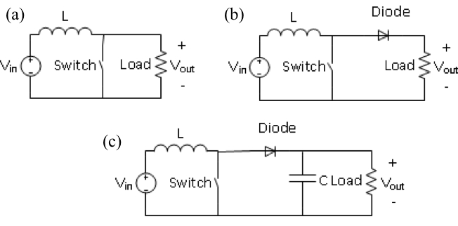
This simple boost converter circuit consists of an input DC voltage source connected to an inductor and a switch. The switch may be a bipolar transistor, a MOSFET or, other similar electronic device that alternately connects and disconnects the inductor from the common line of the power supply. A blocking diode connects the inductor to a capacitor which filters the ripple in the output voltage. Increasing the capacitance decreases the ripple. For a sufficiently large capacitance the output becomes a steady DC voltage. A digital pulse train opens or closes the switch. The pulse has a duty ratio which is the ratio of the on time to the period. The duty ratio may vary from zero or increase up to one with more and more on time. When the pulse is on, the switch closes and the inductor is connected across the supply voltage. In this state, the inductor terminal connected to the output of the power supply has the higher potential and the terminal connected to the common has the lower potential. Now current flows through the inductor increasing linearly with time for sufficiently high switching frequencies. During this time the inductor voltage is defined to be positive because the slope of the current versus time is positive. The inductor stores energy proportional to the square of the current in its magnetic field. The longer the inductor is connected to the power supply, the more current increases and the more energy it stores. When the switch opens, current through the inductor must continue flowing in the same direction. This current also decreases because the inductor now gives up energy to the load. The inductor voltage becomes negative because the slope of current versus time is negative. As a result, the inductor’s polarity flips and now adds to input voltage “V in” producing a higher potential at the output. The circuit in this state, forward biases the diode and the inductor discharges current, some going to the load, and some going to the capacitor which then stores the charge. When the switch closes again the diode becomes reverse biased disconnecting the inductor from the output and preventing a short circuit of the load. During this time the inductor recharges and in its place the capacitor provides current to the load. This cycle of capacitor charging and discharging produces an average output voltage with some amount of ripple. At sufficiently high switching frequencies, the capacitor’s charge and discharge times are short and the output reaches a steady state voltage with relatively little ripple. This switching cycle repeats indefinitely and is the basis of boost converter operation. Ideally the average output voltage increases as the duty ratio increases and a duty ratio of one generates infinite voltage. However parasitic elements and resistances in the boost converter limit useful values of D to a maximum of about 0.7 or 0.8. If D is sufficiently large, parasitic effects dominate circuit operation and output voltage decreases even as D continues to increase. In the following experiments we will study how a boost converter steps up voltage in continuous conduction mode, also called CCM, a condition when the inductor operates at all times with non zero current.

The output voltage in this experiment is limited to 50 volts DC or less. Use only the specified duty cycles, frequencies, input voltages, and loads. These experiments utilize the HiRel Systems Power Pole Board which is designed for experimentation with different DC to DC converter circuit topologies. With signal supply switch S90 turned off, plug the +/- 12 volt signal supply into den connector J90. Set the PWM control selection jumpers J62 and J63 to the open loop position. Adjust the DC power supply to positive 10 volts but do not connect the power supply output to the board. Next build the circuit as shown with the lower MOSFET, the upper diode, and the BB magnetic board. Record the value of the inductor on the BB magnetic board. The load resistor is a power potentiometer. Use a multi meter to measure it’s resistance while adjusting it to 20 ohms. Then connect the potentiometer between terminals V1+ and COM. Set switch selector bank S30 as follows: PWM to bottom MOSFET, use onboard PWM, and switched load off. Connect the oscilloscope’s differential probe between terminal 16 which is the gate of the lower MOSFET and terminal 12 which is the source. Turn on switch S90. The pulse train that drives the MOSFET should appear on the scope’s screen. Select the scope’s time axis to display several periods of this wave form. Set frequency adjustment potentiometer RV60 to produce a switching frequency of 100 kilohertz. Set duty ratio potentiometer RV64 so the pulses have an on time of one microsecond which corresponds to a duty ratio of 0.1.

Connect the DC power supply to input terminals V2+ and COM. To measure the inductor current connect the differential scope probe between terminals CS5 and COM. To measure the voltage across load resistor RL, connect the other differential probe between terminals V1+ and COM. The output voltage should be a triangle wave. The upward ramps occur when the boost convertor switch is open and the inductor is transferring energy to the load. The downward ramps occur when the switch is closed, the inductor is disconnected from the output, and the capacitor is supplying energy to the load. The inductor current is a triangle wave which ramps up linearly during the on time of the pulse train, then ramps down linearly during the off time. The offset is the average current. Using the scope’s built in measurement functions, measure the mean value of the output voltage and the mean value of the inductor current. Repeat these steps with the input DC power supply set to eight, 12, and 14 volts. For a fixed duty ratio as the input voltage increases the output voltage of an ideal boost converter should increase proportionally.

This part of the experiment measures the duty ratio of the pulse train instead of the inductor current. Connect the scope probes between terminals 16 and 12 which are the gate and source of the lower MOSFET respectively. Connect the input DC power supply to terminals V2+ and COM. Like before, the output voltage is a triangle wave resulting from the inductor and capacitor alternately supplying current to the load. The gate source voltage of the MOSFET is a digital pulse train with a frequency of 100 kilohertz, a period of 10 microseconds, and an on time of one microsecond. Measure the mean value of the output voltage and the on time of the gate to source voltage along with the input current and voltage readings from the DC power supply. Repeat this test after adjusting duty ratio potentiometer RV64 so the pulse stream has an on time of two, four, and six microseconds, which correspond to duty ratios of 0.2, 0.4, and 0.6 respectively.

As duty ratio D increases, the output voltage of the boost converter also increases. Ideally if D has a value of 0.2 then an input of 10 volts generates an output of about 12.5 volts. If D is 0.4 then the output would be about 16.6 volts. If D is 0.6 then the output would be about 25 volts. In general, the output voltage is less than expected from the ideal relationship because parasitic elements create non ideal voltage drops and unaccounted energy loss. As the duty ratio approaches one, the theoretical output voltage becomes infinitely large. In reality, the output voltage is limited to about three or four times the input voltage and the influence of parasitic and non ideal components causes the output voltage to decrease after D becomes sufficiently high.

Boost converters generate an output voltage that is greater than the input voltage and many applications incorporate them to increase flexibility in the choice of power sources. The voltage from a solar panel changes with the position of the sun, weather conditions, and shade. Boost converters are commonly used to step up the variable output of a solar panel array to provide a consistent voltage to feed into an electrical grid. Battery powered systems are frequently used to power devices without the use of a power cord. In order to achieve the necessary higher output voltage, battery cells are often stacked. This can take up a lot of space if many cells are needed to reach the desired output. Instead, boost converters are used to step up the voltage while conserving space.

You have just watched Jove’s Introduction to Boost Converters. You should now understand how boost converters work and how adjusting input voltage, duty ratio, and frequency affects the output voltage. Thanks for watching.

Tags

Cite This
JoVE Science Education Database. JoVE Science Education. DC/DC Boost Converter. JoVE, Cambridge, MA, (2023).