Presented here is a protocol for mechanical fatigue testing in the case of human red blood cells using an amplitude-modulated electrodeformation approach. This general approach can be used to measure the systematic changes in morphological and biomechanical characteristics of biological cells in a suspension from cyclic deformation.
Red blood cells (RBCs) are known for their remarkable deformability. They repeatedly undergo considerable deformation when passing through the microcirculation. Reduced deformability is seen in physiologically aged RBCs. Existing techniques to measure cell deformability cannot easily be used for measuring fatigue, the gradual degradation in cell membranes caused by cyclic loads. We present a protocol to evaluate mechanical degradation in RBCs from cyclic shear stresses using amplitude shift keying (ASK) modulation-based electrodeformation in a microfluidic channel. Briefly, the interdigitated electrodes in the microfluidic channel are excited with a low voltage alternating current at radio frequencies using a signal generator. RBCs in suspension respond to the electric field and exhibit positive dielectrophoresis (DEP), which moves cells to the electrode edges. Cells are then stretched due to the electrical forces exerted on the two cell halves, resulting in uniaxial stretching, known as electrodeformation. The level of shear stress and the resultant deformation can be easily adjusted by changing the amplitude of the excitation wave. This enables quantifications of nonlinear deformability of RBCs in response to small and large deformations at high throughput. Modifying the excitation wave with the ASK strategy induces cyclic electrodeformation with programmable loading rates and frequencies. This provides a convenient way for the characterization of RBC fatigue. Our ASK-modulated electrodeformation approach enables, for the first time, a direct measurement of RBC fatigue from cyclic loads. It can be used as a tool for general biomechanical testing, for analyses of cell deformability and fatigue in other cell types and diseased conditions, and can also be combined with strategies to control the microenvironment of cells, such as oxygen tension and biological and chemical cues.
Red blood cells (RBCs) are the most deformable cells in the human body1. Their deformability is directly related to their oxygen-carrying functionality. Reduced deformability in RBCs has been found to correlate with the pathogenesis of several RBC disorders2. Deformability measurements have led us to a better understanding of RBC-related diseases3. The normal lifespan of RBCs can vary from 70 to 140 day4. Therefore, it is important to measure how their deformability decreases along with the aging process, e.g., their fatigue behavior due to cyclic shear stresses3.
Measuring RBC deformability at high throughput is challenging because of the piconewton scale forces (~10-12 N) that are applied to the individual cells. Over the past decade, many technologies have been developed to measure cell deformability5. Deformation measurements of RBCs at the single-cell level can be performed by pipette aspiration and optical tweezers, while bulk analyses are done by osmotic gradient ektacytometry. Ektacytometry analyses provide an abundance of data, which provides an opportunity to diagnose blood disorders6,7. The deformability of RBCs can also be analyzed using the viscoelastic theory by colloid probe atomic force microscopy. In this method, computational analysis is applied to estimate the elastic modulus of RBCs, considering both time-dependent and steady-state responses. The deformability of individual RBCs can be measured by using the single-cell microchamber array method. This method analyzes each cell through the membrane and cytosolic fluorescent markers to provide information for RBC deformability and the distribution of cellular characteristics in complex RBC populations to detect hematologic disorders8.
Fatigue is a key factor in the degradation of properties of engineered materials and biomaterials. Fatigue testing enables a quantitative analysis of the integrity and longevity of a structure subjected to cyclic loading. Analysis of fatigue in biological cells has long been hampered by the lack of a general, readily applicable, high throughput, and quantitative method for the implementation of cyclic deformation in cell membranes. This is possible with the utilization of electrical signal modulation and electrodeformation techniques implemented in a microfluidic setting. The amplitude shift keying (ASK) technique as a digital modulation is applied through On-Off keying (OOK) modulation in this article. The concept of keying refers to the transmission of digital signals over the channel, which requires a sine wave carrier signal to function9. The ON and OFF times can be set equal. Under ON-keying, RBCs enter a deformed state while exposed to an external electrodeformation force (Fdep)10 created by the nonuniform electric field. Under OFF-keying, RBCs are in their relaxed state. We observe the fatigue of RBCs, namely a progressive degradation in their ability to stretch with increasing loading cycles. The fatigue-induced deformability loss in RBCs can provide insights into the accumulated membrane damage during blood circulation, enabling us to further investigate the connections between cell fatigue and disease states.
Here we provide step-by-step procedures on how fatigue testing of RBCs is implemented in a microfluidic device via ASK-modulated electrodeformation and the system settings such as microfluidic device, mechanical loading, and microscopic imagining for the characterization of the gradual degradation in mechanical deformability of RBCs.
Deidentified human whole blood was commercially obtained. Work involving the blood samples was performed in a biosafety level 2 laboratory utilizing protocols approved by the Institutional Biosafety Committee at Florida Atlantic University.
1. Microfluidic device preparation
2. Test fixture
NOTE: The test fixture is designed using 3D CAD software and includes a base housing unit and a top unit (Figure 1B). Then, it is manufactured using a 3-axis CNC milling machine with a standard tolerance limit of around ± 0.005-inch dimension of the test fixture is checked using an electronic caliper (not shown). Sterility of the fixture is not required for the in vitro biomechanical testing.
3. Preparation of electrodeformation working buffer
4. Preparation of cell suspension
5. Electrodeformation setup and fatigue testing
6. Characterization of RBC deformation
When cell suspension was loaded in the microfluidic channel, a relatively uniform distribution of cells was observed. Upon the signal output (e.g., a simple sine wave or On-Keying phase of ASK) from the function generator, the thin-film interdigitated electrodes generated a nonuniform alternating current electrical field. The suspended cells spontaneously responded to this electrical excitation and exhibited a positive DEP behavior, namely moving towards the edges of electrodes with higher field strength. Consequently, cells were aligned along the edges of the electrodes and were stretched due to electrodeformation. Under the On-Keying phase, RBCs are stretched due to electrodeformation; under the Off-Keying phase, RBCs are relaxed (Figure 5B). Maintaining cell discreteness is important in this protocol. Using the dilution factor as stated in this protocol, cell suspension of normal RBCs was in a range of 1 – 6.2 x 10⁴ cells/µL. At a concentration within this range, we were able to obtain a high throughput of cell measurement while minimizing the accumulation of cells due to the positive DEP effect.
When tracking individual RBCs during the 1 h fatigue testing, we observed a gradual decrease in cellular deformation (Figure 5C). Deformability was quantified by the ratio of the major and minor axes of an ellipse that was used to fit the individual RBCs, using open-source imaging software (Figure 6). Images of interest were opened in the software program. It was not necessary to calibrate pixel size into length scale for the deformability measurement. Numerical data can be further analyzed and plotted using software.
In this protocol, deformation data of RBCs was collected in the time interval of 10 min during the 1 h of cyclic mechanical loading using the 250 mHz ASK to modulate the 2 VRMS-3 MHz sine wave. A gradual reduction in cell deformability was observed. The total deformability loss for RBCs under this fatigue testing condition was found to be 18% (Figure 7).
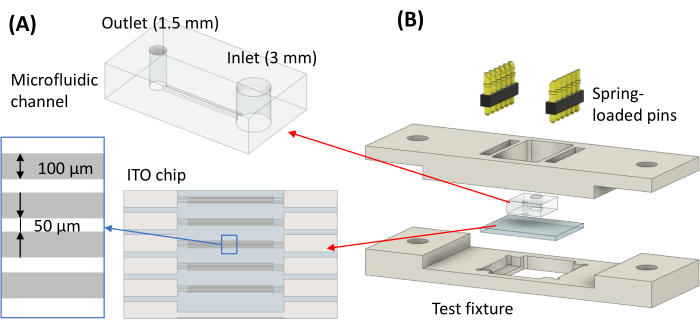
Figure 1: Microfluidic device for electrodeformation. (A) Schematic of the microfluidic channel with biopsy punched holes of 1.5 mm and 3 mm for sample outlet and inlet, respectively. (B) Exploding view of the test fixture assembly. Please click here to view a larger version of this figure.
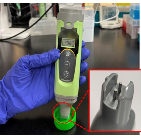
Figure 2: Conductivity meter operation. A conductivity meter was used to verify the conductivity of the DEP medium to be 0.04 S/m. The sensing probes at the base of the meter are submerged in the sample to obtain a reading. Please click here to view a larger version of this figure.
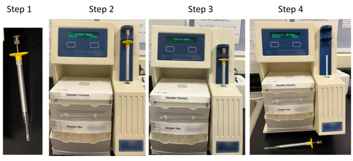
Figure 3: Osmometer operation. An osmometer was used to verify the osmotic concentration of the DEP medium. Step 1 – Snap a sample tip into place on the sampler and load 20 µL of sample. Step 2 – Rest the sampler within the operating cradle and beneath the cradle top. Step 3 – Push the entire operating cradle down until it reaches a positive stop. Step 4 – The instrument runs the test for approximately 1 min and displays the result. Please click here to view a larger version of this figure.
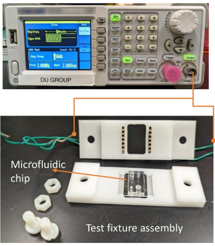
Figure 4: Function generator connectivity. Picture of the experimental setup for fatigue testing, including the test fixture assembly and a function generator. ITO electrode pads are connected to the function generator by BNC-to-alligator clip cable via the wires pre-soldered into the Pogo pin cups pressed into the top unit of the test fixture. The microfluidic device with two independent parallel channels sits on the bottom unit of the test fixture. Please click here to view a larger version of this figure.
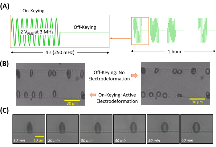
Figure 5: Cell's response to on-off keying. (A) On-off keying modulated sine wave for 1 h fatigue testing: sine wave of 2 VRMS amplitude at 3 MHz for electrodeformation action, modulation frequency of 250 mHz resulting in 2 s of stretching and 2 s of relaxation. (B) Under the On-Keying phase, RBCs are stretched due to electrodeformation; under the Off-Keying phase, RBCs are relaxed. (C) Electrodeformation of a representative cell shows gradual degradation in membrane deformation during 1 h of cyclic stretching. Please click here to view a larger version of this figure.
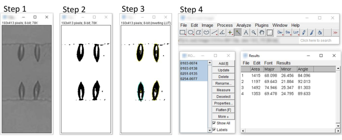
Figure 6: Characterization of RBC deformability using ImageJ. Step 1 – Import the image into image editing software and convert it into 8-bit grayscale. Step 2 – Adjust the threshold to convert images to binary. Step 3 – Select cells with the wand (tracing) tool and manage selections with the ROI manager. Step 4 – Select the cells to obtain measurements for major and minor axes. Please click here to view a larger version of this figure.
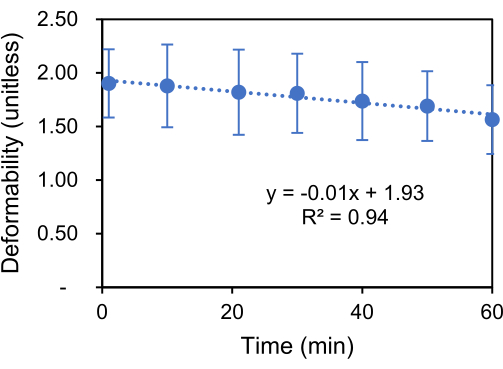
Figure 7: Reduction in cell deformability. Gradual degradation in RBC deformability due to cyclic electrodeformation. The error bar shows the standard deviation (n = 69). Please click here to view a larger version of this figure.
The ASK OOK modulation of a DEP force-inducing sine wave can be used to test the mechanical fatigue of RBCs over a long period of time. In this protocol, we limited the in vitro fatigue testing to 1 hour to prevent the potential adverse metabolic effects on the cell deformability. Comprehensive fatigue testing conditions can be programmed using the ASK-modulated electrodeformation technique. Parameters such as loading frequency, amplitude, and loading rate can all be programmed. The loading frequency can be programmed to varying values to determine the dependence of fatigue on loading frequency as well as differences between cyclic loading and static loading13.
The stretching magnitude can be easily adjusted by using a different voltage level for small or large deformations. However, when using high voltage levels to include large deformation, it is noted that electrodeformation will result in flame-like shaped RBCs (Figure 6, step 3). This can introduce errors when fitting cell shapes with ellipses, which cut off the pointed edges of cells. Under this circumstance, especially when using the electrodeformation to extract membrane shear viscoelasticity parameters, two strategies can be used: (i) using a computational model of true cell shapes will provide more accurate results than the simple analytical elliptical shape model; (ii) using a smaller voltage level to stretch cells so the cell shapes can be well fitted with ellipses.
In the current protocol, the medium conductivity was 0.04 S/m, which can be adjusted as needed. As electrodeformation-induced cellular stretching is related to the real values of the complex Clausius Mossotti factor, the sine wave frequency can be different from the selected 3 MHz. The key is to minimize the voltage to induce electrodeformation while maintaining a negligible Joule heating effect. An optimum electrical excitation can be determined using DEP theory or using computational tools for dielectric modeling of cells, such as My DEP11.
It should be noted that cell immobilization is not required in this protocol as cells undergoing electrodeformation are inherently exhibiting positive DEP, which moves cells to the electrode edges spontaneously. This allows us to perform testing on cell suspensions and immobilize all cells interacting with the electrode and simultaneously stretching the cells. Once the testing is done, cells can be easily removed from the device by flushing the channel with the medium. The characteristic of the current protocol which makes it work well with suspending cells may limit its application to test adherent cells. However, we can detach adherent cells from the substrate using chemicals such as ethylenediaminetetraacetic acid. Since the testing can be designed to be completed in a relatively short time, from minutes to 1 h, we have enough time to perform mechanical fatigue testing before cells anchor and spread14.
In the current protocol, a commercially available ITO chip with 100 µm band interdigitated electrodes was used. Interdigitated electrode design is advantageous for measuring multiple cells at a time for the length-to-area ratio, as the cells are stretched at the edges of electrodes. The throughput of the measurement is also dependent on the field of observation, where cell size and deformability set limitations on the minimum gap of the electrodes. The bandwidth of the electrodes can be further decreased to increase the number of cells of observation for higher throughput. The electrode materials can be other metals, such as titanium or gold; however, the transparency of the electrode materials may be a better choice as part of cell membranes can be blocked by the non-transparent electrodes. The testing can still be performed if a relevant mathematical shape model of the cell, such as an ellipsoid13, can be used during imaging processing.
Theoretically, this electrodeformation and ASK-modulated electrodeformation techniques can work on other cell types, given the right conditions, e.g., medium conductivity and electrical excitations. A limitation is how much elongation we can observe. RBC is a good cell model for its large deformability and circulating nature. The current protocol has been applied to study human RBCs in both health and disease and is readily equipped with a gas microenvironment to study hypoxic fatigue13,15.
The authors have nothing to disclose.
This research has been funded by NSF/CMMI Mechanobiology of Hemoglobin-Based Artificial Oxygen Carriers (#1941655) and NSF/CMMI Dynamic and Fatigue Analysis of Healthy and Diseased Red Blood Cells (#1635312).
Balance Scale | ViBRA | HT-224R | |
Bandpass filter | BRIGHTLINE | 414/46 BrightLine HC | |
BD Disposable Syringes with Luer-Lok™ Tips, 1 mL | Fisher Scientific | 14-823-30 | |
Biopsy Punches with Plunger System, 1.5 mm | Fisher Scientific | 12-460-403 | |
Biopsy Punches with Plunger System, 3 mm | Fisher Scientific | 12-460-407 | 1.5 mm and 3 mm diameter |
Blunt needle, 23-gauge | BSTEAN | X001308N97 | |
Bovin Serum Albumin | RMBIO | BSA-BSH | |
Centrifuge | SCILOGEX | 911015119999 | |
Conical Tube, 50 mL | Fisher Scientific | 05-539-13 | |
Dextrose | Fisher Scientific | MDX01455 | MilliporeSigma™ |
EC Low Conductivity meter | ecoTestr | 358/03 | |
Eppendorf Snap-Cap MicrocentrifugeTubes | www.eppendorf.com | 05-402-25 | |
Excel | Microsoft | Graph plotting | |
Function Generator | SIGLENT | SDG830 | |
Glass/ITO Electrode Substrate | OSSILA | S161 | |
ImageJ | NIH | https://imagej.nih.gov/ij/ | |
Inverted Microscope | OLYMPUS | IX81 – SN9E07015 | |
Lab Oven | QUINCY LAB (QL) | MODEL 30GCE | Digital Model |
Matlab | MathWorks | Graph plotting | |
Micro Osmometer – Model 3300 | Advanced Instruments Inc. | S/N: 03050397P | |
Parafilm Laboratory Wrapping Film | Fisher Scientific | 13-374-12 | |
Petri dish | FALCON | SKU=351006 | ICSI/Biopsydish 50*9 mm |
Phosphate Buffered Saline (PBS) | LONZA | 04-479Q | |
Plasma Cleaner | Harrick plasma PDCOOL | NC0301989 | |
Solidworks | Dassault Systemes | CAD software | |
Sucrose | Fisher Scientific | 50-188-2419 | |
Vacuum Desiccator | SPBEL-ART | F42400-2121 | |
Wooden spatula | Fisher Scientific | NC0304136 | Tongue Depressors Wood NS 6" |