Here, we present a protocol describing a mold-free fabrication process of the polymeric microneedles by photolithography.
This manuscript describes the fabrication of polymeric microneedle (MN) arrays by photolithography. It involves a simple mold-free process by using a photomask consisting of embedded micro-lenses. Embedded micro-lenses were found to influence MN geometry (sharpness). Robust MN arrays with tip diameters ranging between 41.5 µm ± 8.4 µm and 71.6 µm ± 13.7 µm, with two different lengths (1,336 µm ± 193 µm and 957 µm ± 171 µm) were fabricated. These MN arrays may provide potential applications in delivery of low molecular and macromolecular therapeutic agents through skin.
Transdermal drug delivery offers an attractive alternative approach for drug administration, especially for biomolecules, which are almost exclusively administered by hypodermic injections. However, skin, especially the top layer (the stratum corneum), is a formidable barrier preventing exogenous molecules from entering the human body. Recently, MN devices have emerged as enabling tools to deliver drugs through skin. The MN devices create temporary pores inside the stratum corneum to allow the passage of drug molecules to achieve the desired physiological activity with improved patient compliance and convenience1-3.
Various fabrication methods have been adopted to fabricate polymeric MNs4. However, they usually involve complicated and multiple step processes requiring long times and/or high temperatures to fabricate MNs arrays.4 To simplify the fabrication process, a single step mold-free process using a photomask was developed recently5,6. However, with this method, fabricated MNs had blunt needle tips, as no mechanism was in place to modify the ultraviolet (UV) light path involved in photolithography.
In this study, embedded microlenses in the photomask have been proposed to define the geometry of the MNs. The protocol to fabricate photomasks consisting of embedded microlenses and subsequently MN fabrication with sharp tips using the photomask are reported.
1. Photomask Fabrication
2. MN Shafts Fabrication
3. MN Backing Layer Fabrication
The geometry of the MNs can be significantly affected by the photomask characteristics and embedded microlens. The degree of refraction affects the transmission path of the UV rays, which influenced the MN geometry (Figure 2A). Each microlens was found to have a 350 µm diameter, a 130 µm flattened convex surface, and a 62.3 µm depth (Figure 2B-D). Using the Pythagoras theorem, the radius of curvature of the first surface was found to be 272.89 µm. The focal length was calculated to be 509.28 µm (considering nglass=1.53627; nair = 1.000; λ=365 nm) via the lens maker equation12 as stated below:
1/f = (n1/nm-1) * (1/r1-1/r2)
Where n1 is the refractive index of lens material, nm is the refractive index of ambient medium, r1 is the radius of curvature of the first surface, and r2 is the radius of curvature of the second surface.
The effect of UV intensity on the MN length, sharpness and structural deformation was studied by varying intensity of the UV light from 3.14 to 15.1 W/cm2 at a constant focal length and light source distance. It was found that the average MN length significantly increased (p < 0.05) with increasing intensity from 3.14 to 9.58 W/cm2 (Figure 3A). Further increases in intensity up to 15.1 W/cm2 did not produce significant changes in the length. The tip diameter (measure of sharpness) and the MN tip structure were found to vary with increases in intensity (Figure 3B). The MNs with a regular shape and without any structural deformation were observed at 6.4 W/cm2.
The backing layer was fabricated to enable the removal of MN in form of a patch and to make the photomask reusable. It also provided strength to the MN shafts. Therefore, the effect of the backing layer volume (the volume of the prepolymer solutions to form the back layer) was also studied. With unaffected tip diameters, the MNs with a range of the length (1,336 ± 193 µm for 300 µl and 957 ± 171 µm for 400 µl) were observed after the UV exposure (Figure 4).
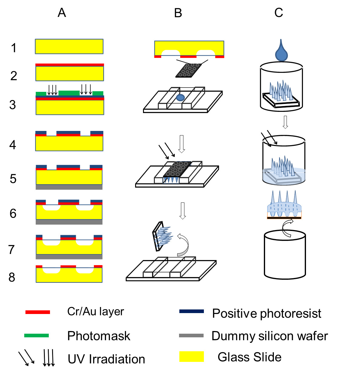
Figure 1. (A) Schematic representation of the fabrication process of lenses embedded photomask. (1) 4” glass wafer. (2) Cr/Au layer deposited using an e-beam evaporator. (3) Exposure of Cr/Au/photoresist masking layer to UV light with photomask. (4) Formation of pattern on layer using Cr/Au etchant. (5) Temporary bonding of glass on a dummy silicon wafer. (6) – (7) Wet etching (isotropic) process using HF/HCl etchants followed by ultrasonication. (8) Debonding of dummy silicon wafer and removal of photoresist layer. (B) Schematic representation of the fabrication process of needles. Chromium coated photomask (9 x 9 arrays), is placed over a cavity containing pre-polymer solution and exposed to UV. (C) Schematic representation of the fabrication process of the backing layer. Photomask, with microneedles attached, is placed in a well filled with pre-polymer and exposed to UV. Please click here to view a larger version of this figure.
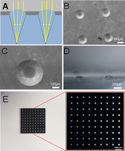
Figure 2. Characterization of photomask. (A) UV exposure focuses light into a conical path, producing tapered MNs. (B) and (C) A SEM image of a microlens. (D) A portion of an array of PDMS mold replicas copied from the microlenses, showing the flattened convex surface, under a stereomicroscope. (E) A photomask showing the pattern. Please click here to view a larger version of this figure.
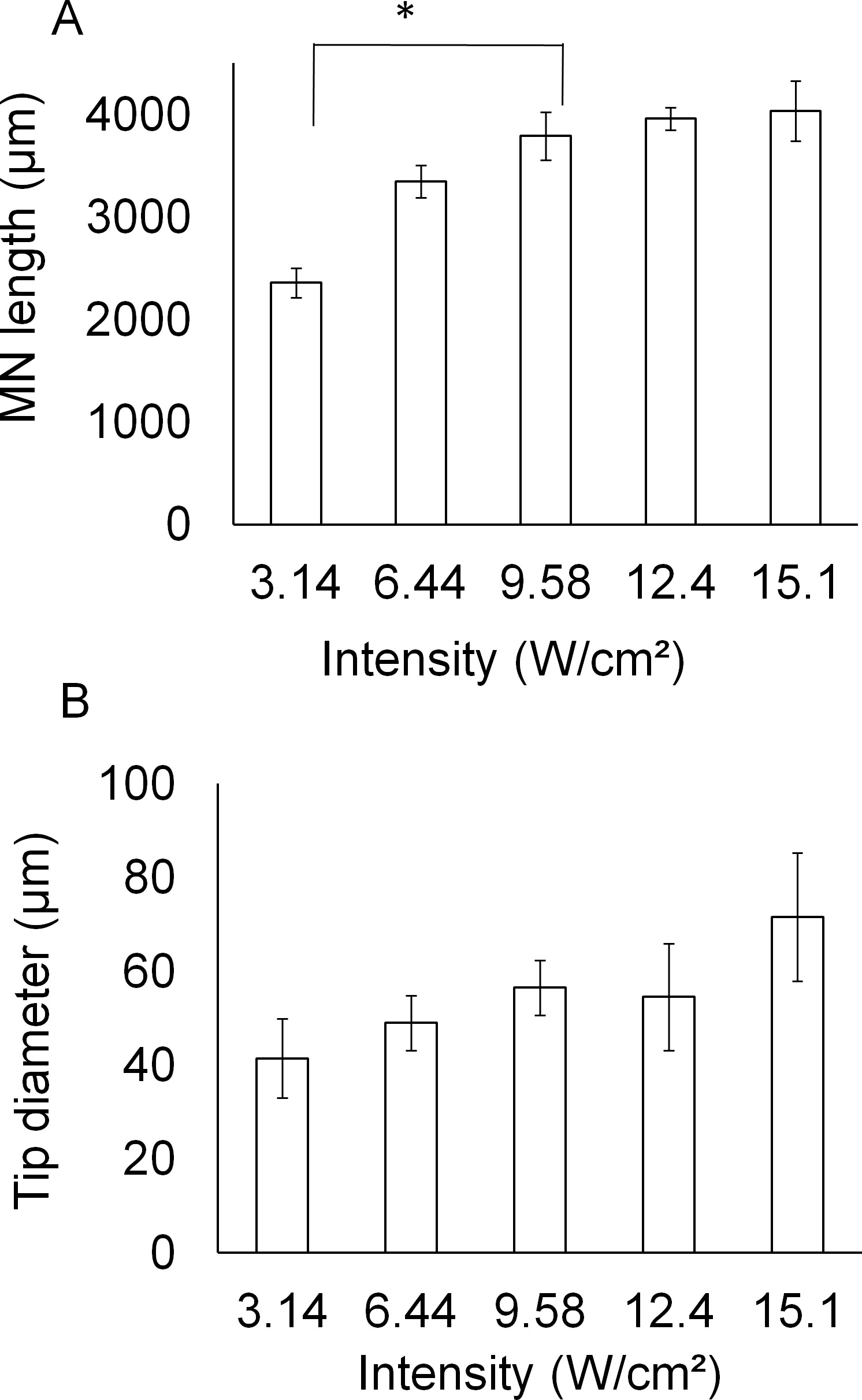
Figure 3. Effect of UV parameters on microneedle geometry. Effect of (A) intensity and (B) spacer thickness on microneedle length. Please click here to view a larger version of this figure.
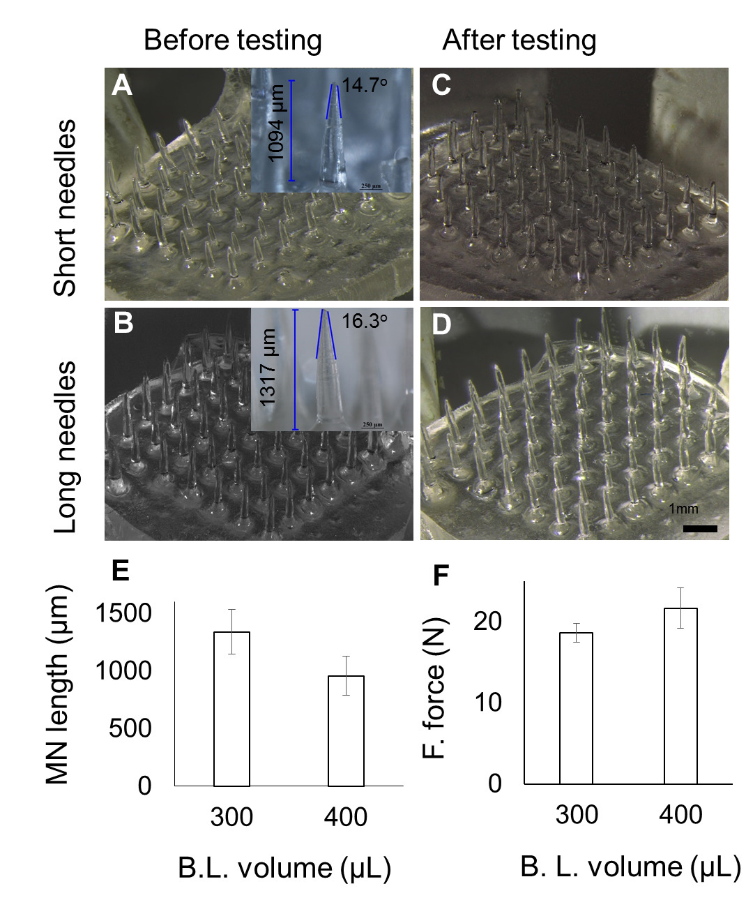
Figure 4. Effect of varying pre-polymer volume used for backing layer fabrication. (A–B) images at various volume, with average MN length for short (957 µm) and long (1,336 µm) MNs. (C–D) Images corresponding to (A-B) after fracture force testing. (E) Decrease in MN length with increase in volume used for backing layer fabrication. (F) MN fracture force across the two pre-polymer volumes used to fabricate backing layer (B.L.). Please click here to view a larger version of this figure.
The protocol described above for fabrication of the MNs array has been presented to fabricate the MNs array of ~1 cm2. The arrays can be scaled up by creating a large size cavity and by using a larger photomask. The increased cavity size can be created by increasing the width between the spacers on either side. Though each step to fabricate the MN arrays in the protocol was important, the most crucial steps were: the photomask positioning, the filling of prepolymer solution, and irradiation of the setup. Positioning of the photomask should be in such a way that the Cr/Au coated surfaces face the interior of the cavity and the sides of the cavity walls obscure the lenses embedded in the photomask. When filling the mold with the prepolymer solution, ensure that air bubbles are not entrapped which can otherwise lead to a deformed and low strength MN array. The air bubbles can be prevented through a controlled wicking action by slowly adding the prepolymer solution and ensuring that there are no air bubbles present in the prepolymer solution. Positioning of the setup for irradiation should be done in a guided manner to ensure uniform UV exposure. Before the exposure to UV light, the setup was aligned and placed within the demarcation on the base stand.
The MNs formed using photolithography were greatly influenced by the presence of the micro-lenses as the lens resulted in polymerization in a converged path, which led to the formation of the sharper MNs as compared to the cylindrical MNs formed using the planar photomask. In the planar photomask, the UV light passes through it with little deviation (almost straight) resulting in formation of the cylindrical MNs with less sharp tips. While in the microlens-embedded photomask, the UV light passing through the lenses underwent refraction and converged, resulting in the formation of sharp tipped MNs. The lens maker's equation which has been used as a predictive model to approximate the length of the MN by correlating with the focal length of the microlens gave a prediction of the length three times less than the real. The discrepancy may be due to the flattened convex surface of the microlens, which did not allow light refraction like the conventional convex lens.13
Another factor for the MN geometry was the UV light intensity. The intensity of 6.44 W/cm2 was chosen because the needles produced at this intensity possessed enough mechanical strength for skin applications. Another finding related to intensity was that with each increment in the UV intensity, the length of MN increases. This could be attributed to the flat top of the microlens, which allowed some of the light rays to travel beyond the focal point.14,15 Furthermore, the extent of polymerization has its limit, depending on the inverse-square law of the light, i.e., the light loses energy as the distance away from the source increases.16
The protocols described here have the advantage of mold-free fabrication within a short period of time. But we cannot predict how far it can be taken further for bulk manufacturing. The MNs arrays were made from a low cost biocompatible polymer. It can potentially be used as transdermal drug delivery device for pharmaceutical and cosmetic applications. More interestingly, it can be used as a combination of the delivery system and device, as the therapeutic compounds may be encapsulated (by mixing or solubilizing in prepolymer solution) during the fabrication of MNs.5,6,17 The solubility of the added compound inside the prepolymer solution should be taken into consideration as the MN characteristics, e.g., MN strength, may change.17
The authors have nothing to disclose.
This study was supported by a Singapore National Research Foundation (NRF) Grant NRF2012NRF-POC001-043.
Poly(ethylene glycol) diacrylate (PEGDA Mn=258) | SIGMA | 475629-500ML | |
2-hydroxy-2-methyl-propiophenone (HMP) | SIGMA | 405655-50ML | |
Bovine collagen type 1, FITC conjugate | SIGMA | C4361 | |
UV curing station | EXFO Photonic Solutions Inc., Canada | OmniCure S200-XL | |
Collimating Adaptor | EXFO Photonic Solutions Inc., Canada | EXFO 810-00042 | |
24-well plate | Thermo Fisher Scientific, USA | ||
Nikon SMZ 1500 stereomicroscope | Nikon, Japan | ||
Dillon GL-500 digital force gauge | Dillon, USA | ||
A-1R confocal microscope | Nikon, Japan | ||