Optical tissue phantoms are essential tools for calibration and characterization of optical imaging systems and validation of theoretical models. This article details a method for phantom fabrication that includes replication of tissue optical properties and three-dimensional tissue structure.
The rapid development of new optical imaging techniques is dependent on the availability of low-cost, customizable, and easily reproducible standards. By replicating the imaging environment, costly animal experiments to validate a technique may be circumvented. Predicting and optimizing the performance of in vivo and ex vivo imaging techniques requires testing on samples that are optically similar to tissues of interest. Tissue-mimicking optical phantoms provide a standard for evaluation, characterization, or calibration of an optical system. Homogenous polymer optical tissue phantoms are widely used to mimic the optical properties of a specific tissue type within a narrow spectral range. Layered tissues, such as the epidermis and dermis, can be mimicked by simply stacking these homogenous slab phantoms. However, many in vivo imaging techniques are applied to more spatially complex tissue where three dimensional structures, such as blood vessels, airways, or tissue defects, can affect the performance of the imaging system.
This protocol describes the fabrication of a tissue-mimicking phantom that incorporates three-dimensional structural complexity using material with optical properties of tissue. Look-up tables provide India ink and titanium dioxide recipes for optical absorption and scattering targets. Methods to characterize and tune the material optical properties are described. The phantom fabrication detailed in this article has an internal branching mock airway void; however, the technique can be broadly applied to other tissue or organ structures.
Tissue phantoms are used widely for system characterization and calibration of optical imaging and spectroscopy instruments, including multimodality systems incorporating ultrasound or nuclear modalities1,2,3,4. Phantoms provide a controlled optical environment for system characterization and quality control of multiple biological imaging techniques. Tissue-mimicking phantoms are useful tools in predicting system performance and optimizing system design for the physiological task at hand; for example, to predict the probing depth of spectroscopic probes for assessing tumor margins5. Optical properties and structural design of the phantoms can be tuned to mimic the specific physiological environment in which the instrument will be used, therefore allowing for both feasibility studies and verification of system performance3,6,7. Verification of imaging system performance with realistic optical phantoms prior to entering pre-clinical or clinical trials reduces the risk of malfunction or acquisition of unusable data during in vivo studies. The reproducibility and stability of optical phantoms make them customizable calibration standards for optical techniques to monitor intra- and inter-instrument variability, particularly in multicenter clinical trials with different instruments, operators, and environmental conditions8,9.
Tissue-mimicking phantoms also serve as tunable and reproducible physical models for validation of theoretical optical models. Simulations aid in the design and optimization of in vivo optical instruments, while reducing the need for animal experiments10,11. The development and validation of optical simulations to accurately represent the in vivo environment can be encumbered by the complexity of the tissue structure, the biochemical content, and the location of the target or tissue within the body. Variability between subjects makes validation of theoretical models challenging using animal or human measurements. Polymer optical tissue phantoms allow for validation of theoretical models by supplying a known and reproducible optical environment in which to study photon migration12,13,14,15.
For the purpose of system calibration, solid optical phantoms may consist of a single homogeneous slab of cured polymer with the optical scattering, absorption, or fluorescence tuned for the wavelengths of interest. Layered polymer phantoms are frequently used to mimic the depth variance of the tissue optical properties in epithelial tissue models16,17. These phantom structures are sufficient for epithelial imaging and modeling, because the tissue structure is fairly homogeneous through each layer. However, larger scale and more complex structures affect radiative transport in other organs. Methods to create more complex phantoms have been developed to simulate the optical environment of subcutaneous blood vessels18,19 and even whole organs, such as the bladder20. Modeling light transport in the lungs provides a unique problem due to the branching structure of the air-tissue interface; a solid phantom would not likely replicate radiative transport in the organ accurately21. To describe a method for incorporating complex structure into an optical phantom, we describe a method to create an internal, reproducible fractal tree void that represents the three-dimensional (3D) macroscopic structure of the airway (Figure 1).
In the past few decades, 3D printing has become a predominant method for rapid prototyping of medical devices and models22, and optical tissue phantoms are no exception. 3D printing has been used as an additive manufacturing tool for fabricating optical phantoms with channels23, blood vessel networks24, and whole-body small animal models25. These methods use one or two printing materials with unique optical properties. Methods have also been developed to tune the optical properties of the printing material to mimic general, turbid biological tissue25,26. However, the range of achievable optical properties are limited by the printing material, usually a polymer such as acrylonitrile butadiene styrene (ABS)26, so this method is not suitable for all biological tissues. Polydimethylsiloxane (PDMS) is an optically clear polymer that can be readily mixed with scattering and absorbing particles with a higher level of tunability27,28. PDMS has also been used to mold phantoms with aneurysm models for deployment of embolic devices29,30. These phantoms also utilize a dissolvable 3D printed part, but remain optically clear for visualizing device deployment. Here, we combine this method with tunability of the optical properties of PDMS with scattering and absorbing particles to fabricate a preliminary model of the tissue and airways of the murine lung.
While the phantom presented here is specific to the lungs, the process can be applied to a variety of other organs. 3D printing of the internal structure of the phantom allows the design to be customizable for any purpose and printable scale, whether it be a blood or lymph vessel network, bone marrow, or even the four chambered structure of the heart31. Because we are interested in optical imaging and modeling of the lung32,33,34, we have opted to use a four-generation fractal tree as the internal structure to replicate within the polymer phantom. This structure was designed to approximate the branching structure of the airway and have break-away support material for the 3D printing process. A more anatomically correct airway could be printed if break-away support material is not necessary. Although this particular model represents an airway, the internal structure of the phantom does not have to remain a material void. Once the surrounding polymer is cured and the 3D printed part is dissolved, the internal structure can be used as a flow pathway or as a secondary mold for a material with its own unique absorption and scattering characteristics. For example, if the internal structure from this protocol was designed as a digital bone rather than an airway, the bone structure could be 3D printed, molded with PDMS with optical properties of the finger, and then dissolved out of the phantom. The void could then be filled with a PDMS mixture with different optical properties. Additionally, each mold is not limited to a single dissolvable part. A phantom of the finger could be created to include bone, veins, arteries, and a general soft tissue layer, each with its own unique optical properties.
1. Selection and Verification of Matrix Material Properties
2. Preparation of Dissolvable 3D Printed Internal Structure
3. Construction of Heat Resistant Mold
NOTE: Prepare a leak-proof, heat-resistant mold to form the PDMS phantom. Select a mold geometry to best fit the final phantom design. Here, a reusable rectangular mold is described.
4. Fabrication of Polymer Phantom
NOTE: Use the verified recipe for the bulk matrix material determined in step 1 for the specific application. The protocol here provides the steps for a healthy murine lung tissue phantom at 535 nm with µs' of 40 cm-1 and µa of 2 cm-1. It may be useful to fabricate a second phantom with no optical particles to use as a reference in the fabrication process.
5. Verification of Phantom Fabrication
To demonstrate the phantom fabrication technique, mouse lung tissue phantoms were fabricated to simulate measured optical properties of excised healthy and inflamed murine lung tissue at 535 nm (Table 5). This wavelength of interest is the excitation wavelength for tdTomato fluorescent protein used in recombinant reporter strains of mycobacteria in previous studies33. Optical measurements of mouse lung tissue were obtained with the same methods described in steps 1.4–1.5. Use of animals was approved by the Institutional Animal Care and Use Committee (IACUC) at Texas A&M University. A suitable ratio of TiO2 to India ink was found for both healthy and inflamed murine lung tissue for 535 nm wavelength light (Table 5).
Recipes for materials with different optical properties are shown in Tables 1-4 and graphically in Figures 2–3. The dependence of absorption and scattering on particle concentration are summarized in Figure 4. Trends in absorption coefficient and reduced scattering coefficient for phantoms with a constant concentration of TiO2 (scattering particle) (Figure 4A, 4B) and a constant concentration of India ink (absorbing particle) (Figure 4C, 4D) demonstrate the relation of optical properties to both particles. To ensure reproducibility of these optical properties, proper mixing technique must be used. Settling and ribboning of TiO2 particles will cause a shift in the scattering coefficient of the cured phantom (Figure 5). India ink staining the mixing container will also reduce the absorption coefficient.
The lung phantoms were designed using a fractal tree structure for the internal void (Figure 1C). The 3D printed structure must be vapor polished to create a smooth internal surface inside the phantom (Figure 1E). Figure 6 shows a comparison of light scattering from a phantom that was not degassed or vapor polished (Figure 6A, C), and a phantom that had a vapor polished internal part and was degassed (Figure 6B, 6D). The phantoms were imaged using illumination from an external white light source (Figure 6A, 6B) and with an internal microendoscope source at 535 nm (Figure 6C, 6D). Vapor polishing and degassing minimize the presence of irreproducible scatterers, including surface roughness (Figure 6C, inset 2) and bubbles (Figure 6C, inset 1). Degassing is particularly important, because air bubble location is random and unpredictable. Furthermore, air bubbles are obscured once TiO2 particles are incorporated (not shown in Figure 6), making the phantom optically opaque. Therefore, unseen bubbles may undermine the phantom material's representation of tissue optical properties.
The vapor-polished 3D printed part was measured with calipers at the base and at the distal branches, and dimensions are compared to the 3D solid model in Table 6. Following fabrication of the polymer phantom, the phantom was imaged using a micro-CT imaging system (Supplemental Material 3). Using the 3D dataset, dimensions of the internal void at the base and distal branches were measured for comparison (Table 6). The vapor polished tree is slightly smaller at the base because the smoothing of the surface by the acetone vapor causes the surface of the plastic to flow. With the 3D printed part suspended by the base, the surface flows towards the distal branches, causing a small change in dimension of the part. There is a trade-off between surface smoothness and maintaining part size. A longer vapor polish will result in a smoother surface, but will cause more material to flow, resulting in altered dimensions.
Phantoms were imaged in an in vivo imaging system with an access port for insertion of a microendoscope fiber bundle (Figure 7). The microendoscope was placed into the void within the phantoms from which the printed part had been dissolved. The microendoscope was used for internal illumination at 535 nm and the IVIS illumination pathway was blocked. The placement of the microendoscope is indicated in Figure 7A. The IVIS was used for external collection of signal. Phantoms imaged had the same internal structure as those imaged in Figure 3. With identical internal structures and external dimensions, the difference in optical properties between healthy lung tissue (Figure 7A) and infected lung tissue (Figure 7B) is apparent in the surface irradiance of the phantoms. As these phantoms maintain an appropriate response to a change in optical properties, this method for phantom fabrication can be applied for phantoms used in internal illumination studies.
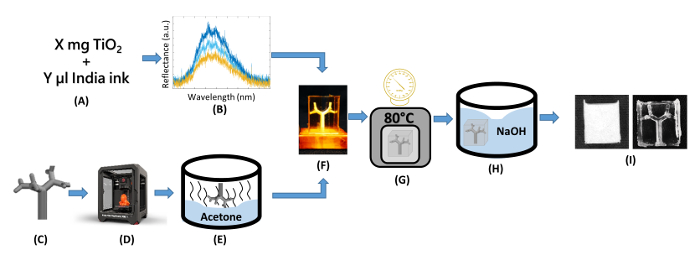
Figure 1: Flow diagram of fabrication of optical tissue phantom. (A) Determine optimal recipe for target optical properties of tissue of interest. (B) Verify recipe. (C) Design internal structure. (D) Print internal structure using dissolvable material. (E) Vapor polish printed part to smooth surface. (F) Mix polymer and optical particles, and pour into heat-resistant mold. (G) Degas and cure polydimethylsiloxane (PDMS). (H) Dissolve printed part to create internal void. (I) Verify phantom geometry and optical properties. Please click here to view a larger version of this figure.
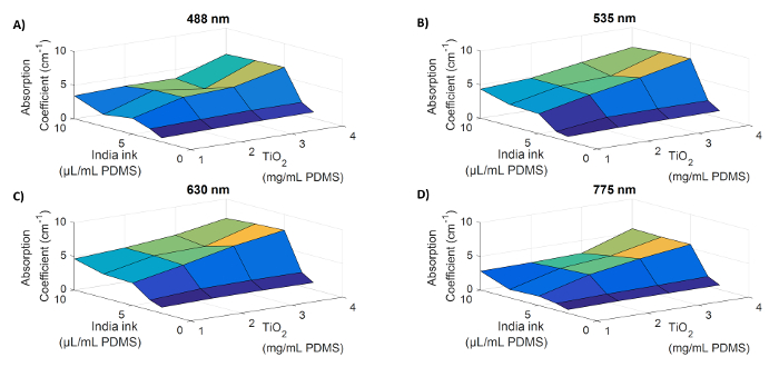
Figure 2: Trends in absorption coefficient for India ink and TiO2 concentration. Absorption coefficients are shown for a range of India ink and titanium dioxide concentrations at 488 nm (A), 535 nm (B), 630 nm (C), and 775 nm (D). Absorption is low for low concentrations for both particles, and generally increases with concentrations of each particles. A plateau is reached between 5–7.5 µL India ink per mL PDMS. The rate of increase depends on the concentration of the other particle and the wavelength. Please click here to view a larger version of this figure.
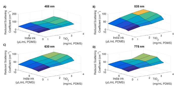
Figure 3: Trends in reduced scattering coefficient for India ink and TiO2 concentration. Reduced scattering coefficients are shown for a range of India ink and titanium dioxide concentrations at 488 nm (A), 535 nm (B), 630 nm (C), and 775 nm (D). The reduced scattering coefficient is low for low concentrations for both particles, and generally increases with concentrations of each. Like absorption, the rate of increase depends on the concentration of the other particle and the wavelength. Please click here to view a larger version of this figure.
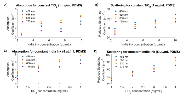
Figure 4: Interdependency of optical properties on India ink and TiO2 concentration. Absorption coefficients and reduced scattering coefficients are shown for recipes with a constant TiO2 concentration of 1 mg/mL PDMS (A, B) and constant India ink concentration of 5 µL/mL PDMS (C,D). Panel (B) shows that scattering coefficient will change with a constant TiO2 concentration when India ink concentration is varied, and panel (C) shows that absorption coefficient will change for a constant India ink concentration when TiO2 is varied. Please click here to view a larger version of this figure.
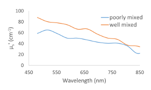
Figure 5: Mixing effects on optical scattering. Improper mixing of the uncured polymer and optical particles can result in a shift in the optical properties. The poorly mixed phantom represented in this figure showed settling of TiO2 particles prior to curing. Please click here to view a larger version of this figure.
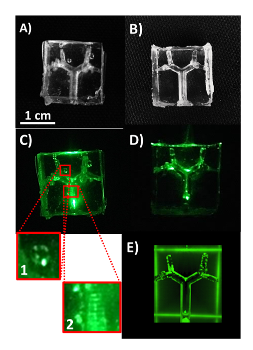
Figure 6: Representative airway phantoms with low scattering coefficient material to illustrate successful and suboptimal fabrication. Vapor polishing and degassing are integral steps in producing a phantom that has minimal uncharacterized scattering elements. (A-B) White light images of phantoms without vapor polishing and degassing (A) and with vapor polishing and degassing (B). (C-D) Phantoms from A-B are illuminated with 535 nm light. Insets from (C) are shown to depict scattering effects of 1) air bubbles and 2) a rough 3D printed surface. (E) Rendering of an optical simulation based on the computer aided design (CAD) model used for the phantom fabrication. Please click here to view a larger version of this figure.
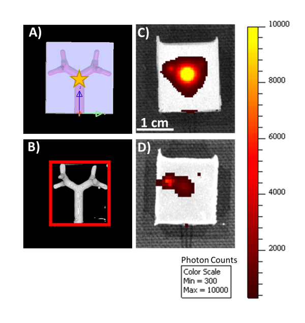
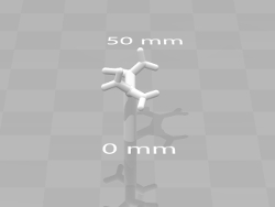
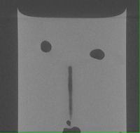
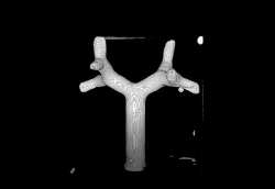
Figure 7: Imaging of phantoms with internal illumination. A computer simulation of the phantom (A) demonstrates the orientation of the internal geometry and source placement (yellow star) for the phantom images in panels (C) and (D). A segmented micro-CT scan of the healthy lung tissue phantom (B) confirms the internal structure is present in the optically opaque phantom. The mock airway is used as a pathway for the endoscope for internal illumination of the optical phantoms at a wavelength of 535 nm. The two phantoms imaged with internal illumination are identical in external shape and internal structure, with material optical properties optimized for healthy (C) and inflamed (D) lung tissue. All images and renderings are on the same scale. Scale bar = 1 cm (panel C). Please click here to view a larger version of this figure.
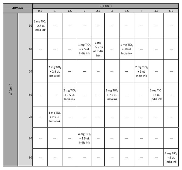
Table 1: Look-up table for 488 nm.
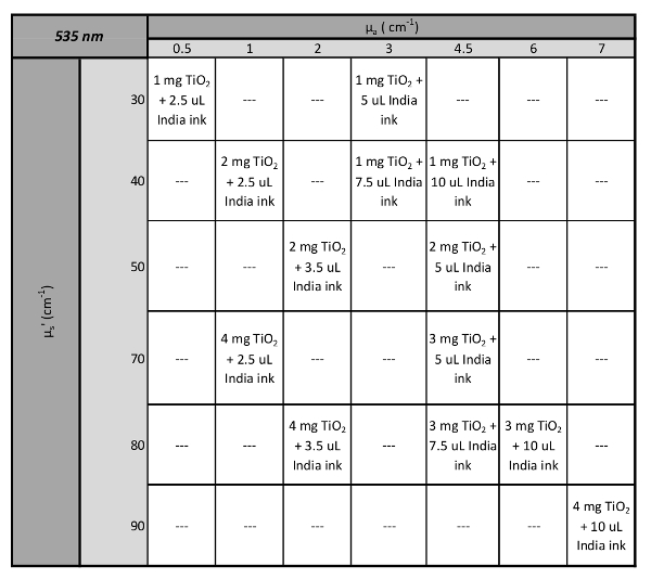
Table 2: Look-up table for 535 nm.
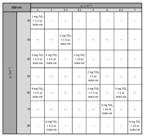
Table 3: Look-up table for 632 nm.
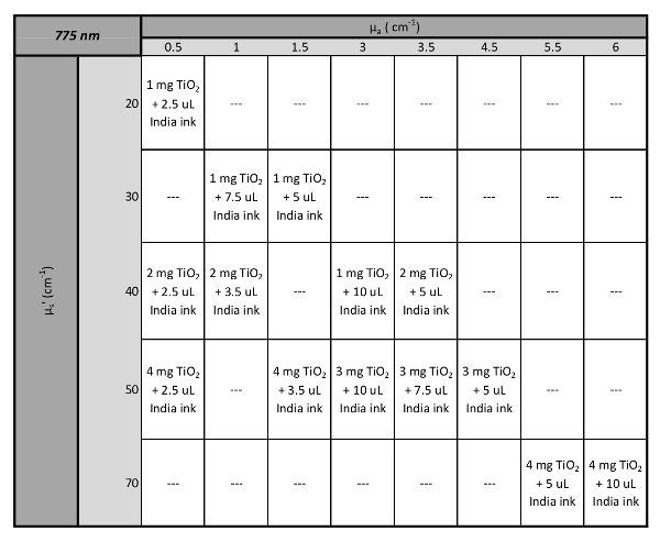
Table 4: Look-up table for 775 nm.
Absorption Coefficient (cm-1) | Reduced Scattering Coefficient (cm-1) | |
Healthy mouse lung tissue | 2.05 ± 0.58 | 52.69 ± 7.83 |
Healthy phantom (2 mg TiO2 + 3.5 µL India ink) |
1.96 ± 0.699 | 49.66 ± .12 |
Inflamed mouse lung tissue | 5.49 ± 1.32 | 38.94 ± 9.68 |
Inflamed phantom (1 mg TiO2 + 10 µL India ink) |
4.34 ± 0.873 | 39.56 ± 5.02 |
Table 5: Measured optical properties of phantom recipes correspond to the measured optical properties of healthy and inflamed mouse lung tissue at 535 nm.
Base diameter (mm) | Distal branch diameter (mm) | |
Solid model | 2.7 | 1.38 |
Vapor polished print | 2.56 ± 0.026 | 1.38 ± 0.141 |
PDMS mold (measured from CT) | 2.55 ± 0.021 | 1.39± 0.055 |
Table 6: Verification of the internal structure of the phantom.
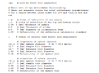
Supplemental Material 1: Example IAD input file. Please click here to download this file.
Supplemental Material 2: Fractal tree airway solid model. Please click here to download this file.
Supplemental Material 3: Micro-CT fly-thru of phantom modeling healthy mouse lung tissue. Please click here to download this file.
Supplemental Material 4: Video of rotating segmented micro-CT scan. Please click here to download this file.
We have demonstrated a method for creating optical phantoms to represent a murine lung with an internal branching structure to simulate the internal air-tissue interface. The optical properties of murine lung tissue are achieved by incorporating unique concentrations of optically scattering and absorbing particles distributed homogenously within the bulk matrix polymer. These optical properties can be tuned to mimic the physiological values within different spectral ranges of tissues in different states (i.e. healthy versus diseased tissue). The optical properties are dependent on the wavelength of interest, the base material, and the concentrations of the particles within the phantom. However, with multiple particles, the relationship between scattering and absorption is not always intuitive41. The rate of increase of absorption is dependent on the concentration of the scattering particle as well as the absorbing particle, and likewise for the rate of increase of the reduced scattering coefficient. (Figures 2-4). PDMS phantoms have also been shown to maintain their optical properties for up to 1 year27,28. We have measured a 3-week stability of optical properties within the error of our integrating sphere measurements (<15%). Storage of these phantoms and standards in a light-tight container can help preserve their optical properties for longer periods of time.
Vapor polishing the dissolvable printed part allows for a reproducible smooth surface on the internal air interface of the phantom (Figure 6). For the fractal geometry shown here, polishing the internal structure yielded a decrease in average surface roughness of molded PDMS from 37.4 µm to 7.2 µm. This is extremely important if the phantom is used for validation of an optical simulation because a rough surface is much more difficult to accurately simulate than a smooth, uniform surface (Figure 6E). Degassing is also very important due to the fact that bubbles within the PDMS phantom act as optical scatterers (Figure 6C, inset 1). Bubble location is not predictable to replicate in a simulation, and could skew results if the phantom is used as a calibration standard.
After verification with micro-CT, a small amount of residual material was found within the airway void (Supplemental Material 3). Additionally, a segmentation of this same CT scan reveals a small air bubble next to the branching structure (Supplemental Material 4). During fabrication, optically clear phantoms yielded a full dissolution of the material of the internal structure and no air bubbles within the polymer matrix. Verification with micro-CT showed that the optically opaque phantoms may contain small flaws, not otherwise visible.
Properly mixing the optical particles with the uncured polymer is imperative to achieve reproducible and predictable optical absorption and scattering. A shift in the reduced scattering coefficient caused by poor mixing is shown in Figure 5. Before pouring the polymer into the mold, ensure there is no evidence of TiO2 particles settling or "ribboning" in the mixture and no evidence of India ink staining the mixing container. Adding the particles in the recommended order should minimize these problems.
The design of these phantoms is limited by the 3D printed part. The mock airway is designed so that the support material can be pried off, as it is not dissolvable. This can be overcome by moving to a more advanced printer that can either print materials with varying solubility, or a laser sintering printer, that does not need support material. It is also important to note that the lung is inherently a very porous organ because of the distal airways and the alveoli. While that is not represented in this phantom, the optical effects of similar structures have been observed using a Bragg-Nye bubble raft for optical coherence tomography21, air bubbles in olive oil42, and shaving cream or dish detergent for nuclear magnetic resonance imaging43. Creating polymer foams with reproducible characteristics may be able to reconcile this difference between the solid phantoms presented here and the lung microstructure44.
The shape of the final phantom can also be customized depending on the application. The rectangular phantom shown here was imaged with internal illumination and used for validation of a computational model of healthy and infected lungs (Figure 7). This design can be updated further to represent the cylindrical torso of the mouse by simply changing the design of the external polymer mold.
While we have detailed here the design of a murine lung and airway phantom, these methods can be modified to fit other organs or animals of interest. The internal structure can be converted to a flow pathway for vascular phantoms, or can be used as a cast for a complex internal structure with unique optical properties. The overall shape of the phantom can also be tuned to the application, animal, or organ of interest. 3D printing of both internal structures and polymer molds gives freedom to the design process of structured polymer optical phantoms. These are integral tools in simulation validation and calibration of in vivo optical imaging techniques, because they can more accurately represent the in vivo environment than homogeneous single or multi-layer phantoms.
The authors have nothing to disclose.
This work was supported by the National Science Foundation CAREER award no. CBET-1254767 and National Institute of Allergy and Infectious Diseases grant no. R01 AI104960. We gratefully acknowledge Patrick Griffin and Dan Tran for their assistance with characterization measurements and the Texas A&M Cardiovascular Pathology Laboratory for micro-CT imaging.
Dow Corning Sylgard 184 Silicone Encapsulant Clear 0.5 kg Kit | Ellsworth Adhesives | 184 SIL ELAST KIT 0.5KG | Polydimethylsiloxane: polymer base for optical phantoms |
White Rutile Titanium Dioxide powder | Atlantic Equipment Engineers | TI-602 | Scattering particles for optical phantoms |
Higgins Fountain Pen India Ink | Michaels Craft Stores | 10015483 | Absorbing particles for optical phantom |
Heat Resistant tape | Uline | S-7595 | Heat resistant tape for polymer molds |
Fortus 360mc 3D printer | Stratasys | N/A | Able to switch build and support material with this model printer |
ABS Ivory Model Material | Stratasys | SDS-000001 | Material for printing mold parts and/or using as support for printing internal structure |
SR-30 Soluble Support | Stratasys | 400638-0001 | Base soluble support material for printing internal structure |
Flacktek Speedmixer | Flacktek Inc. | DAC 150.1 FV | For efficient mixing of polymer and particles |
Integrating sphere | Edmund Optics | 58-585 | For measuring optical properties |
Polycarbonate build plates (1 mm) | Stratasys | N/A | Used polycarbonate build plates from Stratasys printer can also be used |