1. Simulation of EFs and MFs
NOTE: Simulation of EFs and MFs was performed in COMSOL Multiphysics.
- Select an axisymmetric 2D configuration to represent both domains electric and magnetic.
- In the physic configuration, select either the Electric Current interface to compute EFs in parallel electrodes or the Magnetic Field interface to compute MFs around coils.
- In the study configuration, select Frequency Domain to compute the response of a linear or linearized model subjected to harmonic excitation for one or several frequencies.
- Once inside the interface to start building the model, follow the next steps according to the model of the interest.
- Building a model for EFs
- Create geometries. In the Model Builder, select Geometry. Then, locate the Units section and choose mm. On the Geometry Toolbar, select Rectangle and type the dimensions of each component in the Size and Shape box of the Rectangle Window settings . The geometry is composed by air, two parallel electrodes, a culture well-plate, culture media and a biological sample, which in this case is represented by a scaffold of hyaluronic acid – gelatin hydrogel (see dimensions of each element in Table 1). Once all geometries are built, click Build All Objects.
- Create selections. On the Definitions Toolbar, click Explicit to create a selection for the metal domain. Select the geometries that represent the electrodes. After, right-click on Explicit 1 to rename it. Type Metal in the new label text field.
- On the other hand, on the Definitions Toolbar, click Complement. Locate the Input Entities section in the Complement Settings window. Then, under Selections to invert, click Add and select Metal in the Selections to invert list from the Add dialog box. Thereafter, right-click in Complement 1 to rename it. Type Model domain in the new label text field.
- Create boundaries. Click Explicit on the Definitions Toolbar. After, locate the Input Entities section in the Settings window for Explicit and from the Geometric entity level list, choose Boundary. Here, select all boundaries for the bottom electrode. Right-click Explicit 2 to rename it. Type Ground boundaries in the new label text field. Repeat these steps but selecting all boundaries for the upper electrode. Thereafter, right-click Explicit 3 to rename it. Type Terminal boundaries in the new label text field.
- Add electric currents. In the Model Builder window, under Component 1 click Electric Currents (ec). Then, locate the Domain Selection section in the Electric Currents Settings window. From the Selection list, choose Model domain. On the Physics Toolbar, click Boundaries and choose Ground. After, locate the Boundary Selection section in the Ground Settings window and choose Ground boundaries from the Selection list.
- Thereafter, click Boundaries and choose Terminal on the Physics Toolbar. Finally, locate the Boundary Selection section in the Terminal Settings window and choose Terminal boundaries from the Selection list; here, locate the Terminal section and choose Voltage from the Terminal list and type 100 V.
- Add materials. Click Add Material on the Home Toolbar to open the Add Material window. Search air and stainless-steel and add them to the Model Builder window. Then, click Blank Material on the Home Toolbar and add three new blank materials for culture media, scaffold (hydrogel) and polystyrene (culture well-plate).
- Select a blank material to assign the dielectric properties. Locate the Material Properties list in the Material settings window and select relative permittivity and electric conductivity from the Basic Properties option list. The dielectric properties for culture media, hydrogel and culture well-plate are in Table 2. Repeat this procedure for all blank materials.
- Assign each material to the geometries previously built. Select the air material form the Model Builder window; then, select the domains that correspond to air from the Graphic window. Repeat this step for all materials created. Make sure that each domain corresponds to the correct material. To make sure that all materials are correctly assigned, click on each material from the Model Builder window and observe whether the domains are highlighted in blue within the Graphic window.
- Build mesh. Right-click Mesh 1 in the Model Builder window and select Free Triangular. Repeat this step by selecting Size. In the Mesh Setting window select Mesh Controlled by the User from the Sequence Type list. Then, expand the Mesh options in the Model Builder window and click Size.
- Locate Element Size Parameters in the Size Setting window and type 1 mm for maximum element size, 0.002 mm for minimum element size, 1.1 for maximum item growth rate, 0.2 for curvature factor and 1 for resolution of narrow regions. Then, expand the Mesh options in the Model Builder window and click Free Triangular 1. Here, select all domains to be meshed. Finally, click Build All in the Mesh Setting window.
- Create study. Click Study 1 in the Model Builder window. Then, locate the Study Settings section in the Study Settings window and clear the Generate default plots check box. Expand the Study 1 node in the Model Builder window and click Step 1: Frequency Domain. Finally, locate the Study Settings section in the Frequency Domain Settings window and type 60 kHz in the Frequencies text field.
- Calculate study. Click Show Default Solver on the Study toolbar. Then, expand the Study 1 Solver Configurations node in the Model Builder window. Expand the Solution 1 (sol1) node in the Model Builder window; thereafter, click Stationary Solver 1 in the Stationary Solver Settings window and locate the General section and type 1e-6 in the Relative Tolerance text field. Finally, click Compute on the Study Toolbar.
- Plot results. Select Results section on the Home toolbar and add 2D Plot Group. Then, right-click 2D Plot Group 1 in the Model Builder window and choose Surface. Then, locate the Data section in the Surface Settings window and select Precursor. After, locate the Expression section in the Surface Settings window; here, click in the plus (+) symbol to open a new window and locate the follow route from the selection list (Model – Component 1 – Electric Currents – Electric). Here, select ec.normE – EF Norm. Finally, click on Graphic in the Surface Settings window to plot the results.
- Building a model for MFs
- Create geometries. In the Model Builder, select Geometry; then, locate the Units section and choose mm. On the Geometry Toolbar select Rectangle and type the dimensions of each component in the Size and Shape box of the Rectangle Window Settings . The geometry is composed by air and cooper (see dimensions of each element in Table 1). Once all geometries are built, click Build All Objects.
- Add materials. Click Add Material on the Home Toolbar to open the Add Material window. Search air and copper and add them to the Model Builder window. The dielectric properties for copper are in Table 2.
- Create boundaries. Click Magnetics Field on the Model Builder window. Here, locate Equation list on the Magnetic Fields Settings window and choose Frequency Domain equation from the Equation Form list. In Frequency list choose From solver. After, locate Ampere's Law on the Magnetic Field list in the Model Builder window. In the type 293.15[K] in Temperature, 1[atm] in Absolute Pressure from the Inputs Model list. Then, choose Solid from the Material type list in the Ampere's Law Settings window. Make sure that Electric conductivity, Relative permittivity and Relative Permeability correspond to the From material in the list.
- Locate Axial Symmetry on the Magnetic Field list in the Model Builder window. Make sure that the axial symmetry line is highlighted in both Boundary Selection list and Graphic window. Then, locate Magnetic Isolation on the Magnetic Field list in the Model Builder window. Make sure that boundaries from the geometry are highlighted in both Boundary Selection list and Graphic window.
- Locate Initial Values on the Magnetic Field list in the Model Builder window. Select geometries previously built and include them in the Domain Selection from the Initial Values Settings window.
- Introduce coil features. Locate Multiple Coil on the Magnetic Field list in the Model Builder window. Here, selects the geometry that represents the coil and include them in the Domain Selection from the Multiple Coil Settings window.
- Locate the Multiple Coil list on the Multiple Coil Setting window; here, locate Coil excitation list and select Current; thereafter, type 1[A] in the Coil current list, 450 in the Number of turns and 6e7[S/m] in the Coil conductivity.
- Locate the Coil wire cross-sectional area and choose North American cable diameter (Brown & Sharpe) from the list and type 18 in the AWG option. Make sure that Relative permittivity and Relative Permeability correspond to From material in the list.
- Build mesh. In the Mesh Setting window select Mesh Controlled by the physics from the Sequence Type list. After, locate Element Size Parameters in the Mesh Setting window and select Extremely fine. Finally, select all domains to be meshed and click Build All in the Mesh Setting window.
- Create study. Click Study 1 in the Model Builder window. Then, locate the Study Settings section in the Study Settings window and clear the Generate default plots check box. Expand the Study 1 node in the Model Builder window and click Step 2: Frequency Domain. Finally, locate the Study Settings section in the Frequency Domain Settings window and type 60 Hz in the Frequencies text field.
- Calculate study. Click Show Default Solver on the Study toolbar. Then, expand the Study 1 Solver Configurations node in the Model Builder window. Expand the Solution 1 (sol1) node in the Model Builder window; thereafter, click Stationary Solver 1 in the Stationary Solver Settings window and locate the General section and type 1e-6 in the Relative tolerance text field. Finally, click Compute on the Study Toolbar.
- Plot results. Select Results section on the Home toolbar and add 2D Plot Group. Then, right-click 2D Plot Group 1 in the Model Builder window and choose Surface. Then, locate the Data section in the Surface Settings window and select Precursor.
- Locate the Expression section in the Surface Settings window. Here, click in the plus (+) symbol to open a new window and locate the follow route from the selection list (Model – Component 1 – Magnetic Field – Magnetic). Here, select mf.normB – Magnetic flux density Norm. Finally, click on Graphic in the Surface Settings window to plot the results.
- Building a model for EFs
2. Design and manufacturing of the electrical and magnetic stimulation devices
- The electrical stimulator device
NOTE: It is composed by a circuit based on the Wien Bridge Oscillator and two parallel stainless-steel electrodes. The circuit is a RC oscillator of phase shift, which uses a positive and negative feedback. The Wien Bridge Oscillator is composed by a lead-lag network, which divides the input voltage by the combination of two arms of the bridge: a resistor R5 with a capacitor C2 in series, and a resistor R6 with a capacitor C3 in parallel (Figure 1A). These components modulate the frequency of the oscillator. To build the electrical stimulator device follow the next steps:- Calculate the frequency using the resonant frequency equation (1).

Where R = R5 = R6 are resistors and C = C2 = C3 are capacitors. Both R and C are placed in the two arms of the bridge (Figure 1A). Use R5 = R6 = 2.6 kΩ and C2 = C3 = 1 nF to obtain a frequency of 60 kHz. Resistors and capacitors may be calculated if a different frequency is required. - Design the circuit in such a way that voltage gain of the amplifier automatically compensates the amplitude changes of the output signal. In Figure 1A it is possible to observe the scheme of the circuit, while in Table of Materials section are listed the electronic components to build the circuit.
- Calculate the combination of resistors to generate the four output voltages. As shown in Figure 1A, use a combination of resistors R11, R12, R13 and R14 (equivalent resistance of 154 Ω) to generate a voltage of 50 Vp-p; resistors R17, R18 and R19 in series (equivalent resistance of 47,3 Ω) to obtain a voltage of 100 Vp-p; resistors R9 and R10 in series (equivalent resistance of 25,3 Ω) to generate a voltage of 150 Vp-p; and a combination of resistors R15 and R16 (equivalent resistance of 16,8 Ω) to obtain a voltage of 200 Vp-p.
- Use a transistor (TIP 31C) and a ferrite core transformer to implement a signal amplification stage. A toroidal ferrite core was used to wind an AWG 24 copper wire, completing a relation 1:200. Use two capacitors (C4 and C5) of 100 nF in parallel before the transformer to rectify the signal (Figure 1A).
- Prepare the PCB using a third-party PCB manufacturing service. The schematic diagram of the circuit is provided in Figure 1. Place all components on the PCB with antistatic tweezers. Use tin solder and soldering iron to solder all components.
- Manufacture a plastic case with input connectors to protect the circuit. Implement three input connectors to energize the circuit (12 V, -12 V and ground). Use two input connectors to connect the electrodes. Include three switches to change the resistors combination to obtain the four output voltages. Assemble the electronic circuit into the plastic case (Figure 1B).
- Manufacture two parallel stainless-steel electrodes (200 x 400 x 2 mm) and solder input connectors to each edge. The electrodes are located over Teflon or acrylic supports to eliminate any contact with the metal surface of the incubator (Figure 1C).
- Use an autoclave at 394.15 K (121 °C) for 30 minutes to sterilize the electrodes and use ultraviolet over night to sterilize the wires that are in contact with the incubator.
- Test the electrical stimulation device. Adjust the power supply in series to generate an output voltage of +12 V and -12 V between the ground and positive and negative terminals. Verify the output voltage of the power supply with a multimeter. Connect each output of the power supply in the correct input of the electrical stimulator (+12 V, -12 V and ground). Connect each electrode in the correct input connector of the electrical stimulator. The polarity is not important, as we are working on AC current. Place a culture well-plate between of the electrodes and verify the output signal with an oscilloscope. Adjust the switches of the electrical stimulator to generate the four output voltages (50, 100, 150 and 200 Vp-p).
- Safety recommendations. To avoid any issue when transferring or removing the electrodes from the incubator make sure that cables are not tangled. Disconnect cables from the oscillator before removing the electrodes from the incubator. Never place the electrodes without the acrylic or Teflon supports.
- Calculate the frequency using the resonant frequency equation (1).
- The magnetic stimulator device
- Estimate the number of turns to guarantee a homogeneous MF inside the coil using the equation (2), that describes the MF inside a solenoid coil.
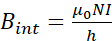
where μ0 is the magnetic permeability of the vacuum (4π×10-7), N is the number of turns of the copper wire, I is the current, and h, which should be greater than its diameter, is the length of the solenoid coil. - Determine the number of turns by choosing a length (h) of 250 mm, current of 1 A and a Bint = 2mT.
- Manufacture the coil. Build a polyvinyl chloride (PVC) tube with a length of 250 mm and a diameter of 84 mm to wind an AWG 18 copper wire completing 450 turns (Figure 2A). Dimensions were chosen based on the available space inside the incubator.
- Manufacture a cell culture well-plate support. Build a polymethyl methacrylate (PMMA) support to ensure that well-plates of 35 mm were always located in the middle of the coil where MFs are homogeneous (Figure 2A).
- Manufacture a transformer to increase the current of the circuit. Build a transformer with an output of 1 A – 6 V AC to reach a maximum MF of 2 mT. The input voltage of the transformer was 110 V AC at 60 Hz. These parameters correspond to the output voltage and frequency of a South America outlet.
- Connect the circuit. The transformer is connected directly to the outlet. Use a variable resistor (rheostat) to vary the current and generate MFs from 1 to 2 mT. Connect a fuse to protect the circuit (Figure 2B).
- Use ultraviolet over night to sterilize the wires that are in contact with the incubator. Wrap the coil with transparent stretch film and use ethanol to sterilize the coil.
- Test the MF device. Use a teslameter to measure the MF magnitude inside the coil. The teslameter probe was located in the center of the coil, allowing the measurement of MFs and currents simultaneously.
- Vary the MF magnitude. Use a rheostat to modify the resistance of the circuit (Figure 2B). A resistance value of 0.7 Ω was used to generate MFs of 1 mT.
- Safety recommendations. To avoid any issue when transferring or removing the solenoid from the incubator make sure that cables are not tangled. Disconnect cables from the transformer before removing the solenoid from the incubator. Never place the solenoid without the PMMA support. Firmly grasp both PMMA support from the base and the solenoid when transferring or removing from the incubator.
- Estimate the number of turns to guarantee a homogeneous MF inside the coil using the equation (2), that describes the MF inside a solenoid coil.
Computational simulation
Distributions of EFs and MFs are shown in Figure 3. On the one hand, it was possible to observe the homogeneous distribution of EFs in the capacitive system (Figure 3A). The EF was plotted to observe in detail the magnitude of the field inside the biological sample (Figure 3B). This simulation was useful to parametrize the size of the electrodes and manufacture them to avoid the edge effect. On the other hand, it was possible to observe the homogeneous distribution of MFs generated by the solenoid coil (Figure 3C). The MF was plotted to observe in detail the magnitude of the field inside the coil (Figure 3D). This simulation was important measure the distance where the MF is the same and build the PMMA support. This support ensures a homogeneous distribution of the MF not only in the center of the coil, but also in the biological samples to be stimulated.
Signals generated by electrical and magnetic stimulators
Output signals generated by electrical stimulator are shown in Figure 4. It is relevant to highlight that signals captured by the oscilloscope were directly taken in the electrodes, as whether the measurement is taken directly to the output cables, the voltages will be higher (Figure 4A). This voltage variation is given by the capacitance of electrodes. The output voltage oscillates in a range of ± 5V at 60 kHz; for instance, the output signals were 54.9 Vp-p (Figure 4B), 113 Vp-p (Figure 4C), 153 Vp-p (Figure 4D) and 204 Vp-p (Figure 4E) for 50, 100, 150 and 200 Vp-p, respectively.
The output signal generated by the magnetic stimulator is shown in Figure 5. The signal captured by the oscilloscope were directly taken in the output cables of the coil (Figure 5A). The output voltage oscillates in range of ± 15V p-p at 60 Hz (Figure 5B).
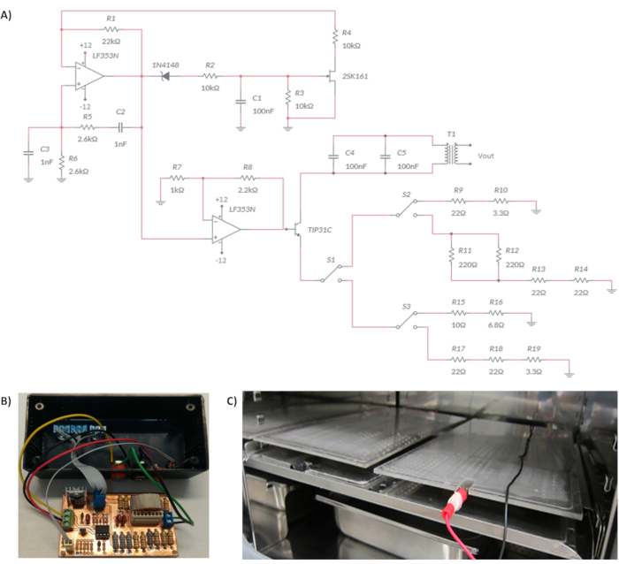
Figure 1. Electrical stimulation device. A) Circuit that generates tensions of 50, 100, 150 and 200 Vp-p at 60 kHz sine wave-form. B) Printed circuit board within the case. C) Electrodes inside the incubator. Please click here to view a larger version of this figure.
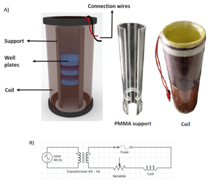
Figure 2. Magnetic stimulation device. A) Schematic representation of the magnetic stimulator device and the PMMA support. B) Circuit to generate the MFs. Please click here to view a larger version of this figure.
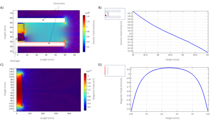
Figure 3. Computational simulation of EFs and MFs. A) Distribution of EFs inside and outside the capacitive system. B) Distribution of EFs within the hydrogel, the region of interest is indicated in a red detail. C) Distribution of MFs inside and outside the coil. D) Distribution of MFs in the center of the coil, the region of interest is indicated in a red detail. Please click here to view a larger version of this figure.
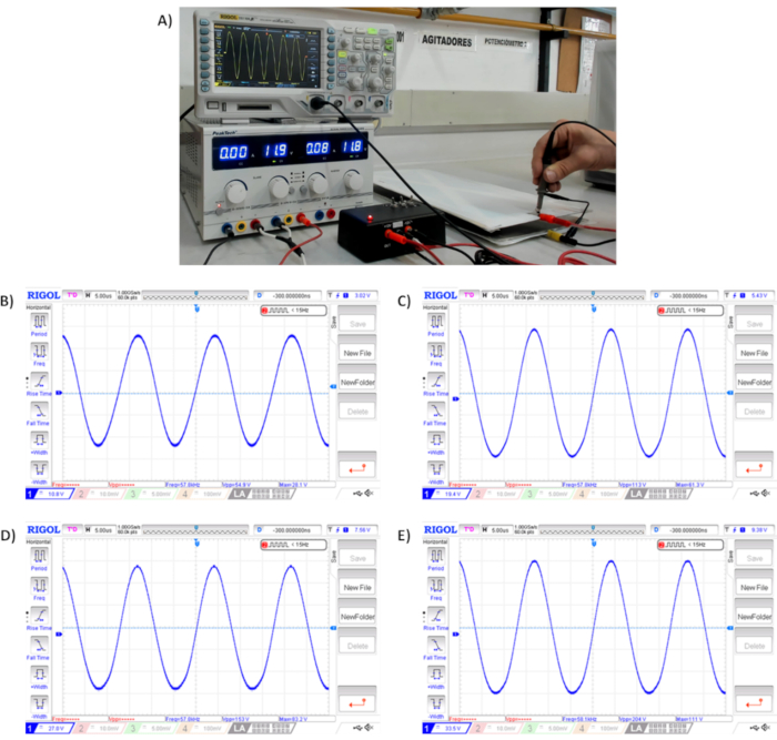
Figure 4. Sinusoidal signal generated by electrical stimulator. A) Signal verification generated by the electrical stimulator. B) Signal at 50 Vp-p. C) Signal at 100 Vp-p. D) Signal at 150 Vp-p. E) Signal at 200 Vp-p. All measurements oscillate in a range of ± 5V at 60 kHz. Please click here to view a larger version of this figure.
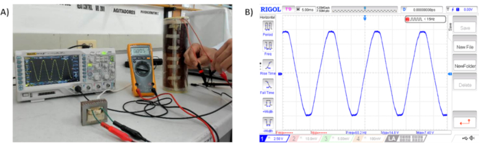
Figure 5. Sinusoidal signal generated by the magnetic stimulator. A) Signal verification generated by the magnetic stimulator. B) Signal at 15 Vp-p at 60 Hz. Please click here to view a larger version of this figure.
| System | Components | Width (mm) | Height (mm) |
| Electrical system | Air | 100 | 100 |
| Electrodes | 50 | 5 | |
| Well-plate | 7 | 20 | |
| Hydrogel | 3.5 | 3.5 | |
| Culture media | 6 | 8 | |
| Magnetic system | Air | 500 | 600 |
| Coil | 2 | 250 |
Table 1. Dimension of geometries that compose electric and magnetic systems.
| System | Components | Relative Permittivity (ε) | Conductivity (σ) |
| Electrical system | Air | 1 | 0 |
| Electrodes | 1 | 1.73913 [MS/m] | |
| Well-plate | 3.5 | 6.2E-9 [S/m] | |
| Hydrogel | 8.03E3 | 7.10E-2 [S/m] | |
| Culture media | 2.67E4 | 7.20E-2 [S/m] | |
| Magnetic system | Coil | 1 | 5.998E7[S/m] |
Table 2. Dielectric properties of elements that compose electric and magnetic systems.
