1. Preparation of Gelatin Containing Substrate for Three-Dimensional Bioprinting of Alginate Hydrogels
- Prepare the calcium/gelatin substrate following the calcium/gelatin substrate method described by Pataky et al11 to avoid reduced viability associated with high content. The calcium/gelatin substrate method is listed below.
- Combine calcium chloride dehydrate (1.5 wt%), sodium chloride (0.9 wt%), and porcine gelatin (2 wt%) in distilled water and boil for 2 min to create a 100 mM gelatin solution.
- Pour 5 ml of the gelatin/calcium solution into 100 mm standard petri dishes, swirl the solution around to make an even coating on the surface, and place on a flat surface in the fridge to gel O/N (allow to gel at least 8 hr before use).
- To increase the opacity of the substrate surface, add titanium dioxide (0.3 wt%) to the gelatin/CaCl2 solution. Stir for 10 min. Autoclave the gelatin/TiO2 solution on the liquids cycle for 30 min to sterilize it.
- Add 3 ml of the gelatin/TiO2 solution to the surface of the previously prepared gelatin plates. Swirl the mixture to ensure it is spread evenly across the surface. Allow to gel in the 4 °C fridge O/N (allow to gel at least 8 hr before use). The substrates must be used within 3 days.
2. Alginate Oxidation
- Oxidize the sodium alginate bioink following the method for partially oxidized alginate by Bouhadir et al30 described below.
- To make a 5% oxidized alginate solution, dissolve 1 g of sodium alginate in 100 ml of distilled water. Add an aqueous solution of sodium periodate (0.25 M, 0.25 mmol), the oxidizing agent, to produce a 5% oxidation solution. Stir for 19 hr at RT. Add 40 ml ethylene glycol to the solution after 24 hr to end the reaction.
- Dissolve 2.5 g of sodium chloride in the solution. Add an excess amount of ethyl alcohol (2:1 ratio) to precipitate the oxidized alginates. Centrifuge the solution at 1,000 x g to collect the precipitates and re-dissolve them in distilled water. Repeat the ethanol wash.
- Freeze-dry the oxidized alginate pellets and store at -20 °C until ready for use.
- Determine the degree of oxidation by measuring the percentage of sodium periodate consumed before being terminated by the ethylene glycol.
- Prepare a potassium iodide solution (20% w/v, pH 7.0 sodium phosphate buffer) and a thyodene solution (10% w/v, pH 7.0 sodium phosphate buffer). Mix the two solutions with the oxidized alginate at RT.
- Gradually drop the reacted alginate and sodium periodate solution into the mixture of potassium iodide and theodyne solutions. Measure the absorbance of the mixture spectrophotometrically at 426 nm. When it has reached a maximum, record the used volume of alginate and sodium periodate solution as V1.
- The reaction is
 . The amount of unreacted sodium periodate is
- Subtract the amount of unreacted sodium periodate from the original concentration to determine the amount of sodium periodate consumed. Using the previous formula, determine the final oxidation degree of the alginate.
3. Alginate Peptide Conjugation
- Conjugate ligands with an exposed arginine-glycine-aspartate sequence ( peptide) into the previously prepared oxidized alginate by following the RGD-Alginate conjugation method by Rowley et al31described below to promote cell attachment and spreading.
- Use aqueous carbodiimide chemistry with G4RGDSPto conjugate31.
- Dissolve 1 g of 5% oxidized alginate in a 0.1 M 2-(N-morpholino) ethanesulfonic acid (MES) buffer, pH = 4. Add 1-ethyl-(dimethylaminopropyl) carbodiimide (EDC, 0.54 mmol) and N-Hydroxysuccinimide (NHS, 0.27 mmol) at 2:1 ratio to form amide intermediate.
- Add 0.28 mmol peptide, coupling to the backbone of the alginate polymer via the terminal amine. Stir at RT O/N.
- Stop the coupling reaction by adding 2.5 g sodium chloride to the solution. Add an excess amount of ethyl alcohol (2:1 ratio) to precipitate the oxidized alginates. Centrifuge the mixture at 4,000 x g for 5 min to collect the precipitates. Aspirate the media in the cell culture hood and re-dissolve the precipitates in distilled water. Repeat the ethanol wash.
- Freeze-dry the precipitates until it becomes completely dried (will appear as a white powdery substance) and store in the -20 °C fridge for later use.
4. Human Adipose Tissue Stromal Cells (hADSC’s) Cell Culture
- Culture human adipose tissue stromal cells (hADSC’s) in 75 cm treated cell culture flasks (T75 flasks), covered with 15 ml low glucose DMEM with 10% fetal bovine serum and 1% penicillin-streptomycin, 1% glutamine, and 1% antimycin. Change the media, in the cell culture hood, every two days until they have reached confluency (80-90%).
- Once confluent, transfer the T75 flasks to the cell culture hood and suspend the hADSC’s using the trypsin enzyme digestion method.
- In the hood, aspirate all of the cell culture media off of the cells. Rinse with 5 ml of Dulbecco’s Phosphate-Buffered Saline with calcium and magnesium (DPBS ++). Aspirate the DPBS++ off of the cells.
- While in the hood, make a solution of trypsin and DPBS++ by mixing 1 ml trypsin and 4 ml DPBS++. Each flask requires 5 ml of the solution, so make the appropriate volume for the number of confluent flasks. Add 5 ml of the trypsin/DPBS++ to each flask and put them in the incubator for 2 min.
- After 2 min, remove the flasks and lightly tap the sides of them to loosen the cells from the bottoms. Look at each flask under a microscope to ensure the cells are suspended. Place the flasks back in the cell culture hood and add 3 ml of appropriate cell culture media to each flask. This ends the trypsin reaction.
- Transfer the cell-laden media from each flask and put in a 50 ml conical. Centrifuge them at 1,000 x g for 5 min. The cells should appear as a little white pellet in the bottom of the conical. Transfer back to the cell culture hood and aspirate the media. Resuspend the cells in 2 ml of cell culture media.
- Count the cells using a hemocytometer under the microscope. Once the cells have been counted, in the culture hood, aliquot the amount of media containing ~1.3 million cells and transfer to a 15 ml conical. Centrifuge the 15 ml conical containing the cells again for 5 min at 1,000 x g.
- In the culture hood, reseed the remaining cells in multiple T-75 flasks, adding a concentration of ~350,000 cells to each flask. Add 15 ml of DMEM media and return to the incubator until confluent again.
- Once the centrifuge cycle is complete, return the 15 ml conical to the cell culture. Aspirate the media from the cell pellet, and resuspend the cells in aqueous alginate solution at a concentration of 1.3 million cells per milliliter of bioink, terteriating the solution often so there is a homogeneous distribution of cells throughout the bioink. Load the cell-laden solution into a sterile printer-compatible 3 ml syringe and screw on the sterile 22 G plastic tip.
5. Bioprinter Setup
- Turn on the bioprinter, each of the dispenser computers, and the recirculating water bath.
- Manually set the recirculating water bath temperature to for the gelation mechanism.
- Manually set printing parameters for each dispenser on the correlating dispenser computer. Set the dispense volume to 230 nl, number of backsteps to 0, and the dispense rate to 10μl –sec.
- Open the design software and the program for viewing the USB camera’s display on the computer.
- Using the software, manually enter the coordinates for a 5 x 5 dot array with 2.4 mm spacing between drops.
- Set the printing parameters to be: distance between tip end and substrate surface = 0.1 mm; height syringe is lifted between depositions = 20 mm; the amount of time per deposition = 1 sec.
- Save the program and send it to the robot.
- Place the gelatin/TiO2-containing Petri dish on the 4 °C printer stage. Close and lock the chamber door.
- Use the PLC to initialize the ultraviolet light sources, and sterilize the chamber for 90 sec.
- Once sterilization is complete, open the chamber and load the syringe containing hADSC’s suspended in alginate into Gun 1. Close and lock the chamber door.
- Use the PLC to turn on the fan system, wait 30 sec for equilibrium internal pressure.
- On the computer, run the program containing the geometrical pathway and printing parameters.
- Throughout the printing process, watch the USB camera’s display on the computer to confirm accurate and uniform printing.
- Once printing has finished, allow the constructs to gel for 40 min.
6. Cell Viability Assessment
- Cover the constructs that are not going to be imaged immediately post-printing in DMEM and store in the incubator until time of imaging.
- To quantify the viability of the constructs, stain them using a fluorescent-based viability/cytotoxicity assay, and image using confocal microscopy.
- Following the kit instructions, prepare a staining solution containing calcein AM and ethidium homodimer-1. To make 10 ml of staining solution, add 20 μl of the ethidium homodimer-1 and 5 μl of the calcein am to 10 ml of sterile, tissue culture-grade Dulbecco’s Phosphate-Buffered Saline (+magnesium, +calcium; DPBS++).
- Immerse the bioprinted constructs in the stain solution for 15 min in the dark.
- Image the stained constructs using a confocal microscope system at days 0 and 8. Take multiple pictures of each bioprinted construct, using Z-stack parameters of 30 optical slices over a 300 μm depth, and manually count the cells. If cells appear yellow or green count them as alive, and if red, count them as dead.
- Calculate the cell viability percentage as the number of live cells divided by the total number of cells in the construct; Cell Viability = number of live cells (green+yellow)/ number of total cells (green+yellow+red) x 100%.
- Calculate the amount of cell proliferation for each sample as the cell number of day 8 divided by the cell number on day 0; Cell Proliferation = live cell count on day 8/ live cell count on day 0 x 100%.
7. RGD Peptide Conjugation Analysis
- To analyze the success of RGD peptide conjugation on the alginate, compare RGD-conjugated alginate and non-conjugated alginate. To do this, image the printed constructs using (4’, 6-Diamidino-2-Phenylindole, Dihydrochloride) (DAPI) and phalloidin stains.
- Make the phalloidins working solution by diluting 5 μl of the methanolic stock solution with 200 μl of DPBS++. Store at -20 °C until use.
- Make a 300 μM stock solution of the DAPI stain following the equation: (0.10509 g/L)/(350.3 g/mol)=3 × 10-4 M=0.0003 M=0.300 mM=300 μM. Make the DAPI working solution by diluting the stock solution 1:100 in DPBS++ to obtain 3 μM solution. Store at -20 °C until use.
- Completely submerge the sample in 4% paraformaldehyde. Incubate for 1 hr at RT. Wash three times with DPBS++, allowing the solution to sit for 5 min each wash. Transfer the gel sample from the well to a glass slide, flipping the gel over in the process. Immerse the gel in 0.1% Triton X-100 (0.1 g/ 100 ml) in DPBS++ for 10 min. Wash three times with DPBS++, allowing 5 min for each wash.
- Stain the printed constructs with phalloidin by immersing them in the working solution. Cover with foil and incubate for 4 hr. Remove the phalloidin stain and wash three times with DPBS++. The first wash should be fast, the latter washes should sit for 5 min each.
- Stain the printed constructs with DAPI by immersing them in the DAPI working solution. Cover with foil and incubate at RT for 30 min. Wash three times with DPBS++, allowing each wash to sit for 5 min. Observe and image the samples on a confocal microscope system.
The results demonstrate the bioprinter is capable of depositing cell-laden hydrogels in specific three-dimensional locations accurately and consistently using computer-aided software. These softwares determine the placement of each droplet and control many of the parameters for dispensing (Figure 3,4). The repeatability of the bioprinter to appropriately deposit biomaterials is fundamental to its success in tissue engineering applications.
Cell viability, one of the requirements of a successful bioprinting technique, was analyzed 1 hr and 8 days post-printing. High cell viability is essential for fabricating biomimetic constructs and is a direct representation of an adequate bioink. RGD peptide conjugation improves cell viability over extended periods of time by promoting cell spreading. Fluorescent microscopy was used to quantify cell viability in constructs after the printing process. Alginate bioink with a concentration of 15% and oxidation of 5% had a day 0 viability of 98%, day 4 of 96%, and day 8 of 95% (Figure 5). These results indicate the deposition technique of the direct-write bioprinter extrudes cells gently enough to produce constructs that remain viable during and after the printing process (Figure 1, 2). The high cell viability shows the 5% oxidation and 15% concentration alginate bioink was a suitable vehicle for cell deposition and provided an adequate environment for cell-survival. Similar cell counts in each of the areas showed a homogeneous cell distribution in the alginate bioink, a fundamental aspect of printing resolution.
Most tissues have complex combinations and gradients of extracellular matrix constituents, each with specific biological and mechanical influences. A biomaterial should be biomimetic of the native environment and facilitate cellular functions. The high porosity of the alginate scaffold allows the cells to communicate and network with each other, and may also facilitate the flux of nutrients and metabolites between the scaffold and its surrounding environment. Cell adhesion to the extracellular matrix is a preliminary phase of tissue formation that happens before cell proliferation and the organization of extracellular matrix molecules into functional tissue. The proliferation of cells plays a vital role in wound healing and tissue growth, and is therefore a very important factor when analyzing bioprinted constructs for tissue engineering applications. The RGD-conjugated alginate enhanced cell attachment in printed constructs, leading to improved cell spreading and proliferation. The proliferation of cells in the printed scaffolds was quantified by counting three separate areas on days 0 and 8 (Figure 6). The overall cell proliferation was found to be 219.674% after 8 days of culture. These results signify the scaffold has adequate biocompatibility to be used as a synthetic extracellular matrix for delivering cells to repair damaged or nonfunctional tissue.
To analyze the success of RGD peptide conjugation on the alginate bioink, a comparison experiment was performed using cell-laden, RGD-conjugated 15% concentration, 5% oxidation alginate bioink and cell-laden, non-conjugated 15% concentration, 5% oxidation alginate bioink. DAPI staining for nuclei and phalloidin staining for actin were used to analyze the cell spreading in printed constructs on day 8. Images of each sample (at least three random pictures per sample) were taking using a confocal microscope system using Z-stack parameters of 30 optical slices over a 300 depth (Figure 7). The cell spreading shown in the sample with RGD-conjugated alginate proves the successful incorporation of the peptide on the alginate. Cell migration is an important step in tissue development; therefore the conjugation of RGD peptides on alginate improves the likelihood of in vivo application using this bioink.
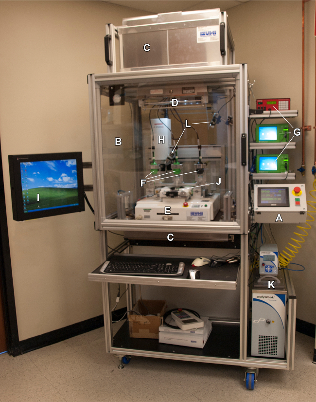
Figure 1. Palmetto Printer. Programmable Logic Controller coordinates the actions of all printer functions (A). An airtight containment chamber (B) with filtered intake (C) and exhaust (C) maintains a regulated internal positive pressure to reduce the chance of contamination. Dual UV lights (D) mounted in the chamber ceiling can be programmed to operate at safe intervals. A Janome 2300N XYZ Robot (E) is programmed and controlled by an integrated computer (I). Three dispenser controllers (G) are programmed to regulate the output of dispenser guns (F) available to be loaded onto the robot Z-axis arm (H) under computer control. The temperature of the robot sample holder (J) is set between 4 and 40 °C by a water bath controller (K). Dual digital cameras (L) are available to monitor printer activity and sample formation. One camera is mounted onto the robot Z-axis arm and provides a magnified image of the dispenser tip of the loaded gun. Please click here to view a larger version of this figure.
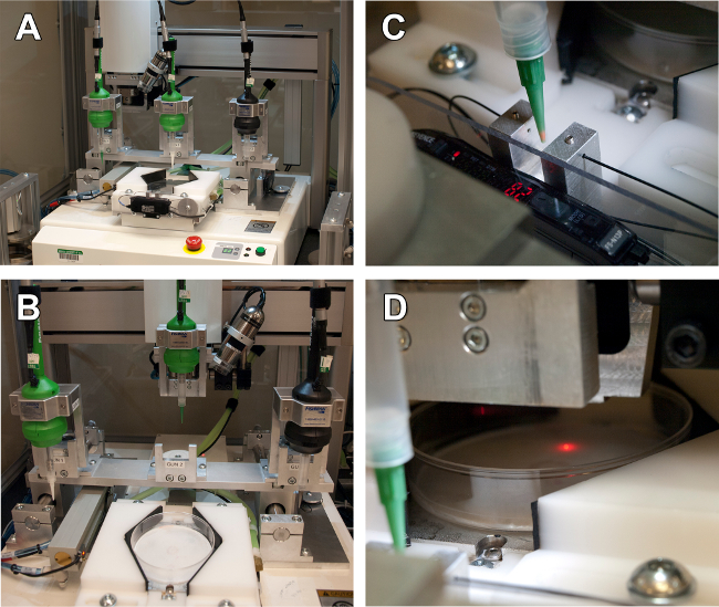
Figure 2. Tool Nest, Optic Sensors, and Displacement Laser of Bioprinter. A. Unloaded tool nest view from the front. B. Loaded tool nest view from the front. C. Optic Sensors measuring the dispensing tip end in three-dimensional space. D. Distance laser measuring the Z coordinate of the printing surface. Please click here to view a larger version of this figure.
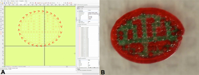
Figure 3. Visual PathBuilder Software. Image of computer-aided design drawing software used for designing the external architecture of bioprinted constructs. This program provides the ability to generate incrementally spaced droplets and complex geometries. Please click here to view a larger version of this figure.
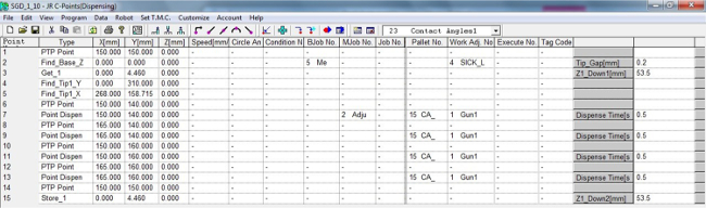
Figure 4. JR-C Points Software. Screenshot of the printer-compatible design software. This program allows the user to control the deposition method (i.e., single drop deposition or continuous pathway deposition), deposition speed, distance between syringe tip end and printing substrate surface, the allotted time for deposition of each drop, and the three-dimensional placement of droplets (refer to Table 1). Please click here to view a larger version of this figure.
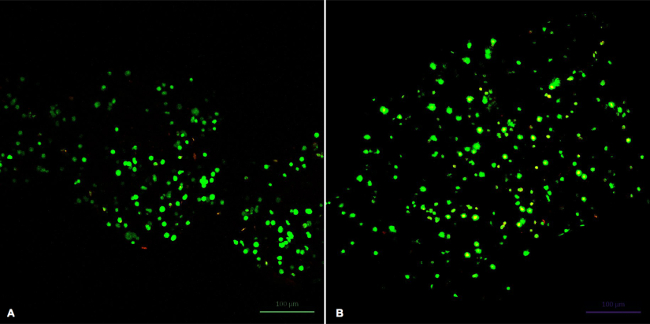
Figure 5. Fluorescent Image of Stained hADSCs Post-Printing. Cell viability/cytotoxicity fluorescent images of hADSC’s in bioprinted construct taken using a confocal microscope system (Z-stack parameters of 30 optical slices over a depth) after 0 (A) and 8 (B) days. The hADSC’s were labeled post-printing using a mammalian cell viability/cytotoxicity assay. Live cells are stained green, and dead cells are stained red. Please click here to view a larger version of this figure.
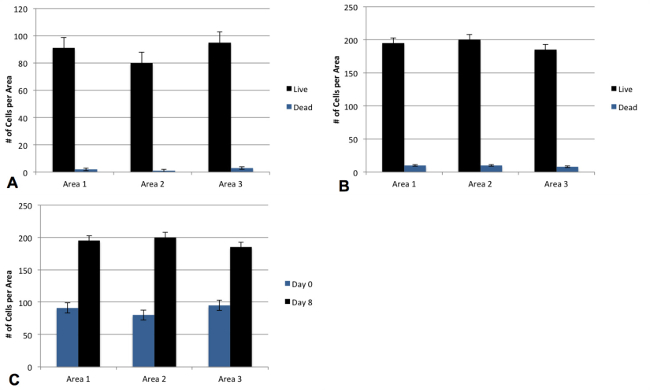
Figure 6. Quantified Viabilities of Bioprinted Constructs. The number of live and dead cells was quantified using a viability/cytotoxicity assay. The live/dead cell counts for Day 0 are shown in (A), and the counts for Day 8 in (B). The number of live cells counted for each area on days 0 and 8 are shown in (C) and were used to quantify cell proliferation. Please click here to view a larger version of this figure.
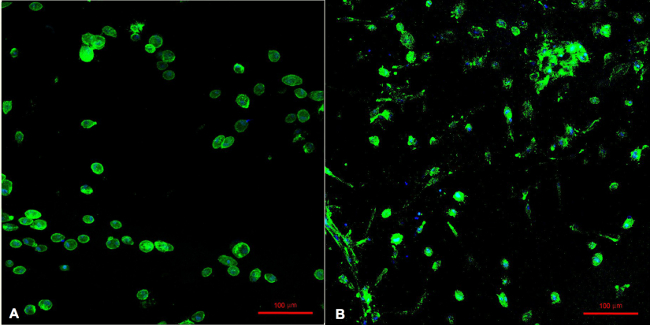
Figure 7. Comparison of Cell-Laden, Non-Conjugated and RGD-Conjugated Alginates. Fluorescent images of bioprinted hADSC’s in non-conjugated (A), and in RGD-conjugated (B) 15% concentration 5% oxidation alginate bioink taken using a confocal microscope system (Z-stack parameters of 30 optical slices over a depth). The hADSC’s were stained with phalloidin and DAPI stains to analyze the cell spreading in each of the constructs. Please click here to view a larger version of this figure.
| Table of Commands | |
| Command | Robot Response |
| PTP Point | Robotic arm moves to indicated posiiton in X, Y, Z space |
| Find_Base_Z | Uses the SICK laser to measure the printing surface of the substrate; The distance between the syringe tip end and substrate surface is manually set. |
| Work Adj. No. (Work Adjustment Number) | Commands robot to use SICK laser (for determining substrate surface), Gun 1, Gun 2, or Gun 3. |
| Get_1 | Commands robot ot retrieve and load Gun 1 |
| Find_Tip1_YZ | The robot finds the tip end of Gun 1 in the Y and Z directions |
| Find_Tip1_X | The robot finds the tip end of Gun 1 in the X direction |
| Point Dispense | The robot will dispense one droplet of bioink in the determined X, Y, Z position |
| Pallet No. (Pallte Number) | Incorporates a manually coded design for printing, e.g., an array. |
| Dispense Time | Is the time allotted for the deposition of each individual drop. |
| Store_1 | Commands the robot to return Gun 1 to the toolnest, and return to home position: (0,0,0). |
Table 1. Programmable Computer Software Commands. This chart outlines the programmable computer software commands, which are used to control the robotic arm and optimize printability parameters.
