Recording Gap Junction Current from Xenopus Oocytes
Summary
Here we present a protocol to express gap junction proteins in Xenopus oocytes and record junctional current between two apposed oocytes using a commercial amplifier designed for dual oocyte voltage-clamp recordings in a high side current measuring mode.
Abstract
Heterologous expression of connexins and innexins in Xenopus oocytes is a powerful approach for studying the biophysical properties of gap junctions (GJs). However, this approach is technically challenging because it requires a differential voltage clamp of two opposed oocytes sharing a common ground. Although a small number of labs have succeeded in performing this technique, essentially all of them have used either homemade amplifiers or commercial amplifiers that were designed for single-oocyte recordings. It is often challenging for other labs to implement this technique. Although a high side current measuring mode has been incorporated into a commercial amplifier for dual oocyte voltage-clamp recordings, there had been no report for its application until our recent study. We have made the high side current measuring approach more practical and convenient by introducing several technical modifications, including the construction of a magnetically based recording platform that allows precise placement of oocytes and various electrodes, use of the bath solution as a conductor in voltage differential electrodes, adoption of a commercial low-leakage KCl electrode as the reference electrode, fabrication of current and voltage electrodes from thin-wall glass capillaries, and positioning of all the electrodes using magnetically based devices. The method described here allows convenient and robust recordings of junctional current (Ij) between two opposed Xenopus oocytes.
Introduction
GJs are intercellular channels that may allow the current flow and exchange of small cytosolic molecules between neighboring cells. They exist in many cell types and perform diverse physiological functions. GJs in vertebrates are formed by connexins, whereas those in invertebrates by innexins. Each GJ consists of two juxtaposed hemichannels with either 6 or 8 subunits per hemichannel, depending on whether they are connexins or innexins1,2,3. Humans have 21 connexin genes4, while the commonly used invertebrate models C. elegans and Drosophila melanogaster have 25 and 8 innexin genes, respectively5,6. Alternative splicing of gene transcripts may further increase the diversity of GJ proteins, at least for innexins7,8.
GJs may be divided into three categories based on molecular compositions: homotypic, heterotypic, and heteromeric. A homotypic GJ has all its subunits being identical. A heterotypic GJ has two homomeric hemichannels, but the two hemichannels are formed by two different GJ proteins. A heteromeric GJ contains at least one heteromeric hemichannel. The molecular diversities of GJs may confer distinct biophysical properties that are important to their physiological functions. GJ biophysical properties are also modulated by regulatory proteins9. To understand how GJs perform their physiological functions, it is important to know their molecular compositions, biophysical properties, and the roles of regulatory proteins in their functions.
Heterologous expression systems are often used to study biophysical properties of ion channels, including GJs, and the effects of regulatory proteins on them. Because heterologous expression systems allow the expression of specific proteins, they are generally more amenable to dissecting protein functions than native tissues where proteins with redundant functions can complicate the analysis, and recording of Ij can be unattainable. Unfortunately, most commonly used cell lines except the Neuro-2A cell are inappropriate for studying GJ biophysical properties due to complications by endogenous connexins. Even Neuro-2A cells are not always appropriate for this kind of analysis. For example, we could not detect any Ij in Neuro-2A cells transfected with the innexins UNC-7 and UNC-9 in either the absence or the presence of UNC-1 (unpublished), which is required for the function of UNC-9 GJs in C. elegans9,10. On the other hand, Xenopus oocytes are a useful alternative system for electrophysiological analyses of GJs. Although they express an endogenous GJ protein, connexin 38 (Cx38)11, potential complications can be easily avoided by injecting a specific antisense oligonucleotide12. However, analyses of GJs with Xenopus oocytes require a differential voltage clamp of two juxtaposed cells, which is technically challenging. The earliest successes of double voltage clamp of frog blastomeres were reported about 40 years ago13,14. Since then, many studies have used this technique to record Ij in paired Xenopus oocytes. However, essentially all the previous studies have been performed with either homemade amplifiers12,15,16 or commercial amplifiers designed for recordings on single oocytes (GeneClamp 500, AxoClamp 2A, or AxoClamp 2B, Axon Instruments, Union City, CA)8,17,18,19,20. Because even the commercial amplifiers do not provide instructions for double oocyte voltage clamp, it is often challenging for new or less sophisticated electrophysiological labs to implement this technique.
Only one commercial amplifier has been developed for double oocyte voltage clamp, the OC-725C from Warner Instruments (Table of Materials, Figure 1A). This amplifier may be used in either a standard mode (for single oocytes) or a high side current measuring mode (for single or dual oocytes) depending on whether two sockets in its voltage probe are connected (Figure 1B, C). However, until our recent study7, there had not been a single publication describing the use of this amplifier in its high side current measuring mode. Although the amplifier has been used by another lab for dual oocyte recordings, it was used in the standard rather than the high side mode21,22. This lack of reports using the amplifier in its high side current measuring mode might be due to technical difficulties. We were unable to obtain stable dual oocyte recordings using the high side mode by following instructions from the manufacturer. Over the years, we have tried three different approaches for dual oocyte recordings, including using two OC-725C amplifiers in the high side current measuring mode, two OC-725C amplifiers in the standard mode, and two amplifiers from another manufacturer. We eventually succeeded in obtaining stable recordings only with the first approach after extensive trial and error. This publication describes and demonstrates the procedures we use to express GJ proteins in Xenopus oocytes, record Ij using the high side current measuring mode, and analyze the electrophysiological data using popular commercial software. Additional information about the double voltage-clamp technique may be found in other publications19,23.
Protocol
The surgeries are performed following a protocol approved by the institutional animal care committee of the University of Connecticut School of Medicine.
1. Frog surgery and preparation of defollicuated oocytes
- Anesthetize an adult female African clawed frog (Xenopus laevis) (Table of Materials) by immersing in a cool (with ice) tricaine solution (~300 mg/L).
- Wait (~15 min) until the frog shows little or no response to squeezing its webbed feet. Lay the frog on an operating table with its belly facing up.
- After a longitudinal incision (8-10 mm long) on either the left or the right lower abdominal region, gently pull out a small piece of ovary tissue with a pair of forceps, and cut free the ovary tissue with a pair of small scissors.
- Immediately immerse the free ovary tissue in a Ca2+-free ND96 solution (NaCl 99 mM, KCl 2 mM, MgCl2 1 mM, HEPES 5 mM, pH 7.5) inside a 60-mm Petri dish.
- After closing the incision by simple interrupted sutures using a 5-0 silk suture (Table of Materials), put the frog back into a shallow water tank for recovery.
NOTE: The incision is closed in two steps: first the peritoneal and muscle layers, and then the skin layer. Each frog is subjected to 5 surgeries with at least a 4-week interval between two consecutive surgeries. - Transfer the isolated ovary tissue to a 50-mL centrifuge tube containing 10 mL of Ca2+-free ND96 solution with 20 mg of collagenase (Table of Materials) and 20 mg of hyaluronidase (Table of Materials).
- Shake the tube on an orbital shaker at room temperature (RT) until all the oocytes have become isolated (solitary).
- Thereafter, transfer 30-50 oocytes to a Petri dish using a glass Pasteur pipette and examine the oocytes frequently under a stereomicroscope (≥25x highest magnification power) to determine whether they are defolliculated.
NOTE: The Pasteur pipette should be "cut" to a wider tip opening using a diamond scriber (Table of Materials) and flamed to smooth the cutting edge. - As soon as 70%-80% of the oocytes are defolliculated, decant the enzyme solution by gently tilting the tube. Wash the oocytes 5 times by filling up the tube with ND96 solution (NaCl 96 mM, KCl 2 mM, CaCl2 1.8 mM, MgCl2 1 mM, HEPES 5 mM, pH 7.5) and decanting the solution.
- After the final wash, transfer the oocytes to a 60-mm Petri dish containing ND96 solution. Pick and transfer large and healthy-looking oocytes to a 60-mm Petri dish containing ND96 solution supplemented with sodium pyruvate (2 mM) and penicillin-streptomycin (100 U/mL) using a clean glass Pasteur pipette.
NOTE: "large and healthy-looking oocytes" are those of stages V and VI showing no sign of over-digestion by the enzymes. - Place the Petri dish containing the picked oocytes inside an environmental chamber (15-18 °C).
2. GJ protein expression
- Synthesize complementary RNA (cRNA) of a specific connexin or innexin in vitro using an RNA transcription kit (Table of Materials) following the manufacturer's protocol.
- Precipitate the cRNA using a lithium chloride method described in the user manual of the RNA transcription kit.
- Wash the pellet with 70% ethanol, dissolve it in 20 µL of nuclease-free H2O, and add 1 µL of ribonuclease inhibitor (40 U, Table of Materials).
- Measure the concentration of the cRNA using a spectrophotometer (Table of Materials).
- Mix the cRNA with a Cx38 antisense oligo so that the final concentrations are 200-1,000 ng/µL cRNA and 100 ng/µL oligo.
NOTE: The oligo sequence is 5′-GCTTTAGTAATTCCCATCCTGCCATGTTTC-3′, which corresponds to the nucleotides from -5 to +25 in Xenopus laevis Cx38 mRNA (NCBI Accession: NM_001088018)11. The oligo is kept as a stock solution (2.0 mg/mL) prior to being mixed with the cRNA. - Eliminate particles in the cRNA by spinning in a microcentrifuge (~16,000 x g) for 2 min, and quickly transfer the entire supernatant to a new tube by pipetting (avoid disturbing the bottom of the microcentrifuge tube).
- Divide the cRNA into aliquots (2.5 µL/vial), and store the aliquots in a -80 °C freezer.
- Prepare an oocyte injection dish by gluing a small piece (~1 cm x 1 cm) of nylon mesh (Table of Materials) to the bottom of a 35-mm Petri dish using a quick-cure epoxy adhesive.
NOTE: The oocyte injection dish is reusable. Wash it with 70% ethanol after each use. - Fill the oocyte injection dish approximately halfway with ND96 solution (supplemented with pyruvate and penicillin-streptomycin).
- Place 25-30 oocytes in rows inside the Petri dish.
- Prepare glass micropipettes for oocyte injections by following instructions in the user manual of the automated nanoliter injector (Table of Materials).
NOTE: Use of a microelectrode beveler (Table of Materials) can help produce sharp injection micropipettes that cause minimum damage to oocytes. - Backfill an injection micropipette with lightweight mineral oil, and insert it into the micropipette holder of the injector.
- Transfer the cRNA from one of the stored aliquots to the inside surface of a Petri dish cover or bottom by pipetting.
- Aspirate the cRNA droplet into the tip of the micropipette by pressing the FILL button in the injector controller.
- Inject the cRNA (~50 nL/oocyte) by pressing the INJECT button.
NOTE: The injection volume may be set by the dip switches in the injector controller. - Transfer the injected oocytes to a new Petri dish containing ND96 solution (supplemented with pyruvate and penicillin-streptomycin), and keep them inside the environmental chamber (15-18 °C) for 1-3 days (depending on GJ protein expression speed and level). Replace the solution daily by transferring the oocytes to a new Petri dish.
3. Oocyte pairing
- Transfer a few of the injected oocytes into a 35-mm Petri dish containing ND96 solution.
- Use two fine tweezers (Table of Materials) to gently peel off the transparent vitelline membrane that wraps the oocyte.
NOTE: It may be necessary to sharpen the tweezer tips before the first use and from time to time, using a piece of fine (600 Grit) sandpaper. - Place 2 oocytes per well in an oocyte pairing chamber (Figure 1D) containing ND96 solution (supplemented with pyruvate and penicillin-streptomycin).
NOTE: The oocyte pairing chamber is constructed by gluing a small piece of a Microwell Minitray (Table of Materials) to the bottom of a 35-mm petri dish (Table of Materials) using a quick-cure epoxy adhesive. The Minitray is cut into small pieces using a hot wire cutter (Table of Materials). Use of the Minitray for oocyte pairing was originally described by others24. Although a GJ protein might distribute non-uniformly in the oocyte cell membrane depending on charge properties of amino acid residues in its cytosolic domains25, random pairing (without discriminating between the animal and vegetal poles of the oocyte) appears to be sufficient in general. - Keep the Petri dish containing paired oocytes at RT on the isolation table to be used for electrophysiological recordings.
NOTE: The pairing duration can vary from a few hours to one day. A convenient practice is to pair oocytes in the late afternoon and record from them on the following day.
4. Acquisition system preparation
- Configure two OC-725C oocyte clamp amplifiers (Table of Materials) to the high side current measuring mode by adjusting an internal dip switch (Figure 1B).
- Ground the amplifiers by first interconnecting the Ground Circuit sockets on the rear panels and then connecting to the Faraday cage and the fiber light used for illuminating the recording chamber.
- Connect the amplifiers to an analog-to-digital signal converter (Table of Materials), and configure them in the Clampex module of the pClamp software (Table of Materials) following instructions from the amplifier manufacturer.
- Test the acquisition system with the model cell supplied with the amplifier.
- Connect the VDIFF probe and current (I) cables to the model cell, connect the Red and Black sockets in the VDIFF probe with the included jumper, connect either leg of the jumper to either pin in the model cell, and connect the ground wire in the model cell to the cable from the GROUNDS CIRCUIT socket of the amplifier (Figure 1E).
- Zero the Voltage Electrode (Vm) and Bath Electrode (Im) meters of the amplifier by turning the Vm OFFSET and Ve OFFSET knobs, respectively, switch Clamp from OFF to either Fast or SLOW and turn the GAIN dial clockwise to a level that allows proper voltage clamp (Figure 1A). The D.C. GAIN switch may be at either the OUT or the IN position.
- Run a simple acquisition protocol containing a few voltage steps to confirm that the voltage displayed in the Vm meter changes according to the acquisition protocol and that voltage and current traces are displayed properly in Clampex.
NOTE: Only one amplifier may be tested each time using this approach.
5. Recording Ij between paired oocytes
- Create acquisition protocols for recording Ij in the pClamp software.
NOTE: Create two acquisition protocols. In one of them, amplifier # 1 is used to produce a series of membrane voltage (Vm) steps (e.g., -150 to +90 mV at 10-mV intervals), whereas amplifier #2 is used to maintain a constant Vm (e.g., -30 mV). In the other protocol, amplifier #2 is used to produce the Vm steps, whereas amplifier # 1 is used to maintain the constant Vm. The positive and negative Vm steps should be applied alternatively (e.g., -150, +90, -140, +80 ……), which can be programmed in Clampex using the User List feature in the acquisition protocol. - Set up the recording stage
- Drop one Petri dish containing paired oocytes into the Petri dish receptacle in the recording platform (Figure 2A)
- Select a pair of oocytes and rotate the Petri dish if necessary so that the two oocytes are in the left and right direction, and lock the stage in position by its magnetic base.
- Fix the magnetic stands holding the current and voltage probes at appropriate locations on the isolation table.
NOTE: Make sure that the current and voltage probes from one amplifier are located on the left side, whereas those from the other amplifier are on the right side, and that the voltage probe is in front of the current probe on each side (Figure 2B, C).
- Set up the reference electrode
- Place a reference electrode (Table of Materials) near the edge of the Petri dish toward the user side (Figure 2B, C).
- Connect the reference electrode to the black socket (Circuit Ground) in only one of the two VDIFF probes.
- Set up the VDIFF electrodes
- Pull a pair of glass micropipettes, break off a bit of the tip with the diamond scriber (Table of Materials), and smooth the tip edge by fire polishing.
NOTE: Tip resistance should be less than 150 kΩ (measured with ND96 in the pipette). Typically micropipettes with tip resistance of 20-150 kΩ are used. - Hold the micropipette above the flame of an alcohol burner to bend it to a smooth angle (~130°) at a position ~1 cm away from the tip.
NOTE: Fabricated micropipettes are reusable. Rinse them with water after each use. - Backfill the glass pipette completely with ND96 solution, insert it into a prefilled (with ND96) microelectrode holder (Table of Materials, Figure 2D), and ensure no air bubbles are present in the system.
- Insert the 2-mm pin of the microelectrode holder into the 2-mm socket of a VDIFF electrode connection wire (Figure 2D).
- Clamp the 2-mm socket on a magnetically based clamper (Figure 2D), and aim the tip of the VDIFF electrode toward one of the two oocytes (Figure 2E).
NOTE: Adjust the position and angle of the clamper so that the tip of the electrode is very close to the oocyte - Insert the 1-mm pin of the VDIFF electrode connection wire into the red socket (VDIFF Input) in the VDIFF probe on the same side.
- Prepare and connect a VDIFF electrode for the other oocyte and amplifier following similar procedures.
NOTE: A close-up view of a pair of oocytes and all the electrodes are shown in Figure 2E.
- Pull a pair of glass micropipettes, break off a bit of the tip with the diamond scriber (Table of Materials), and smooth the tip edge by fire polishing.
- Set up the current and voltage electrodes
- Prepare voltage and current electrodes from glass capillaries, backfill them (about halfway) with a KCl solution (KCl 3.0 M, EGTA 10 mM, HEPES 10 mM, pH 7.4 with KOH), and insert them into the electrode holders provided with the amplifiers.
NOTE: The electrodes should have a resistance of ~1 MΩ. Suitable electrodes may be obtained from a type of thin-wall glass capillaries (Table of Materials) using a specific set of pulling parameters (Table 1). Such tips can easily penetrate the oocyte cell membrane without the need to press either the Vm or the Ve BUZZ button on the amplifier. - Lower the electrodes into the bath solution, zero the Vm and Im meters by turning the Vm OFFSET and Ve OFFSET dials and check electrode resistance by pressing Vm Electrode Test and Ve Electrode Test.
- Insert the current and voltage electrodes into the oocytes, and observe negative membrane potentials (typically -20 to -50 mV).
NOTE: The Vm and Im meters of the same amplifier should display two identical or very similar values.
- Prepare voltage and current electrodes from glass capillaries, backfill them (about halfway) with a KCl solution (KCl 3.0 M, EGTA 10 mM, HEPES 10 mM, pH 7.4 with KOH), and insert them into the electrode holders provided with the amplifiers.
- Data acquisition
- In the Clamp section of the amplifier, confirm that D.C. GAIN is at the IN position, turn the GAIN knob clockwise to a level that allows proper voltage clamp (typically one-third to half of the full range), and turn the Clamp switch from OFF to FAST.
NOTE: Upon turning on the clamp, the Vm and Im meters will display the holding voltage and the holding current, respectively. Although the holding current may vary somewhat depending on oocyte conditions, it is generally small and stable at the holding Vm (e.g., -30 mV). - Run an acquisition protocol.
NOTE: Four traces will be displayed on the screen. The voltage and current traces from one amplifier indicate the Vm steps applied to oocyte #1 and the current needed to produce the Vm steps, whereas those from the other amplifier indicate the constant Vm (-30 mV) of oocyte #2, and the current injected to maintain this constant Vm. The current injected into oocyte #2 represents the Ij.
- In the Clamp section of the amplifier, confirm that D.C. GAIN is at the IN position, turn the GAIN knob clockwise to a level that allows proper voltage clamp (typically one-third to half of the full range), and turn the Clamp switch from OFF to FAST.
6. Data analysis
- Analysis with Clampfit.
- Open a recorded abf file in the Clampfit module of pClamp.
- Use cursors 1 and 2 to enclose a segment of the baseline before the Ij traces.
- Click on the icon Adjust Baseline to bring out a Baseline window. Select Subtract Mean of Cursors 1..2 for Method, and confirm that All Visible Signals and All Visible Traces are selected for Trace Selection.
- Upon clicking OK, the Baseline window closes, the baselines of all the current and voltage traces converge at the zero level. Note that the voltage steps change to new levels that are equal to the original voltage minus the holding voltage (e.g., -30 mV).
- To plot the Ij and Vj relationship using steady-state Ij, enclose a desired segment of the Ij traces representing steady-state Ij with cursors 1 and 2, place cursor 3 anywhere within the time window of the voltage steps.
- Go to Analyze/ Quick Graph/ I-V to open an I-V window.
- Under X-Axis (Voltage), select Cursor 3 from Signal, specify the voltage step signal (e.g., Voltage 1) in the dropdown menu, and check the box Invert.
NOTE: The Invert box is checked to convert the Vm to values equivalent to Vj, which is defined as Vm of oocyte #2-Vm of oocyte #1. - Under Y-Axis (Current), select the source of the Ij signal (e. g., Current 0) from the dropdown menu next to Signal, define Region as Cursors 1..2 from the dropdown menu, and select Mean.
NOTE: To plot peak Ij and Vj relationships, cursors 1 and 2 should enclose the segment of Ij traces containing the peak Ij in step 6.1.5 and select Peak (instead of Mean) in step 6.1.8. - Under Destination option, select either Replace or Append.
- Upon clicking OK in the I-V window, an Ij – Vj relationship is displayed on the screen, and the corresponding Ij and Vj values may be found by clicking Window/Result.
- Plot and fit the Gj–Vj relationship in OriginPro (Table of Materials)
- Copy the two columns containing Vj and Ij values from the Results window of Clampfit (step 6.1.10) to a new Workbook in Origin. Make sure that the Vj and Ij values are under X and Y columns, respectively.
- Add four new columns in the Workbook by clicking Column/ Add New Columns.
- Name the first new column as Gj, fill it by entering the equation "column Ij/column Vj * 1,000" in the Set Column Values window, and create a scatter plot of the Gj–Vj relationship.
NOTE: The multiplication by 1,000 (optional) is to avoid the inconvenience of dealing with very small numbers in subsequent steps. - Fit the Gj data points over the negative and positive Vj ranges independently to the Boltzmann function. Calculate Gj at Vj = 0 mV by entering the Gjmax, Gjmin, A, and V0 values from the fitting into the Boltzmann equation, which can be done in a spreadsheet. The Gj thus obtained will be used as Gjmax in the next step.
NOTE: The equation to fit the Boltzmann function is: Gj = (Gjmax–Gjmin)/{1 + exp[A(Vj–V0)]} + Gjmin, in which V0 is the Vj at which the conductance is half-maximal, Gjmax is the maximal conductance, Gjmin is the Vj-insensitive residual conductance23. To perform the fitting, first add the Boltzmann equation as a new fitting function into OriginPro, and then select this function for fitting. Enter approximate seed values for the Gjmax, Gjmin, V0, and A before executing the fitting function. Make sure that the Gjmax parameter is not fixed for this fitting. - Name the second and third new columns as nGj-L and nGj-R ("n" for "normalized"), and fill them by dividing the Gj column by the Gjmax values derived from the left and right Gj – Vj curves, respectively (step 6.2.4).
- Name the fourth new column as nGj-LR, and fill it by copying values from the negative and positive Vj ranges of the nGj-L and nGj-R columns, respectively.
- Create a scatter plot for nGj-LR over Vj, and fit the data points over the negative and positive Vj ranges to the Boltzmann function independently. Make sure that the Gjmax parameter is fixed at 1.0 for the fitting.
- Keep records of the fitting results (e.g., the fitted graph and the Gjmin, V0, and A values).
Representative Results
UNC-7 and UNC-9 are innexins of C. elegans. While UNC-9 has only one isoform, UNC-7 has multiple isoforms that differ mainly in the length and amino acid sequence of their amino terminals7,8. These innexins may form homotypic as well as heterotypic (of UNC-7 and UNC-9) GJs when expressed in Xenopus oocytes7,8. Representative Ij traces and the resulting normalized Gj–Vj relationships of UNC-7b and UNC-9 homotypic GJs are shown in Figure 3. In these experiments with paired oocytes, Vm of Oocyte 1 were clamped to different levels from the holding voltage (-30 mV), whereas that of Oocyte 2 was kept constant at -30 mV to monitor the Ij. The results show that these two types of GJs differ in the Vj-dependent Ij inactivation rate, Vj dependence (indicated by the slope of the Gj–Vj curve), and the amount of the residual Gj. Many other examples of UNC-7 and UNC-9 GJs, including rectifying GJs, may be found in our recent publication7.
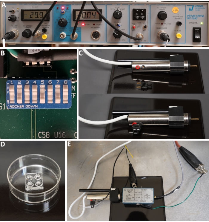
Figure 1: Oocyte pairing chamber and amplifier setup. (A) Front panel of the oocyte clamp amplifier OC-725C. (B) A DIP switch inside the amplifier configured for the high side current measurement. All the toggle switches except 2, 5, and 7 are in the OFF position to use the amplifier in the high side current measuring mode. (C) A VDIFF probe with the red socket (for VDIFF input) and black socket (for Circuit Ground) either unconnected or connected. The probe may be used for the standard voltage-clamp mode when the two sockets are connected. (D) An oocyte pairing chamber. (E) A model cell with connections for testing the acquisition system with the amplifier in the high side current measuring mode. Please click here to view a larger version of this figure.
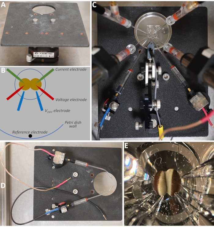
Figure 2: Oocyte and electrode setup. (A) The recording stage. The circular hole has a diameter of 36 mm. (B) Diagram showing the positions of the various electrodes. (C) Actual layout of the various electrodes. (D) Two VDIFF electrodes with their holders and connection cables clamped on the recording stage by two different magnetic clamps, including a modified Agar Bridge Magnetic Holder (Table of Materials) (top) and a tube clamp (Table of Materials) (bottom). The former is more stable in maintaining the electrode position because of its larger magnetic base but requires modification. The glass micropipettes are rotated 90° from their operating positions in order to show the bending angles. (E) A close-up view of a pair of oocytes and the electrodes. Please click here to view a larger version of this figure.
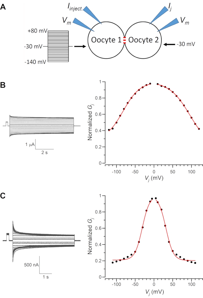
Figure 3: Representative recording traces. (A) Diagram showing the oocyte experiment. Negative and positive membrane voltage (Vm) steps are applied to Oocyte 1 from a holding Vm of -30 mV whereas Oocyte 2 is held at a constant Vm of -30 mV. The transjunctional voltage (Vj) is defined as Vm of Oocyte 2 –Vm of Oocyte 1. (B). Sample Ij traces and the resulting normalized junctional conductance (Gj) –Vj relationship of UNC-9 homotypic gap junctions. (C) Sample Ij traces and the resulting normalized Gj–Vj relationship of UNC-7b homotypic gap junctions. The Gj–Vj relationships are fitted by a Boltzmann function (red lines). Please click here to view a larger version of this figure.
| Step No. | Heat | Pull | Velocity | Time |
| 1 | 260 | … | 40 | 200 |
| 2 | 240 | … | 40 | 200 |
| 3 | 240 | 60 | 40 | 200 |
| 4 | 245 | 100 | 60 | 200 |
| Refer to the user manual at the manufacturer’s website for definitions of the pulling parameters (https://www.sutter.com/MICROPIPETTE/p-97.html). | ||||
Table 1: Electrode pulling parameters. These parameters are based on thin-wall glass capillaries (Table of Materials) and a ramp temperature of 258 at a P-97 micropipette puller (Table of Materials). They need to be adjusted according to the ramp temperature for this glass on your puller. For example, if the ramp temperature on the puller is 20° higher, add 20° to each step and make necessary adjustments. Generally, tip size may be optimized by adjusting the velocity of the last step. Please refer to the user manual at the manufacturer's website for meanings of the pulling parameters (https://www.sutter.com/MICROPIPETTE/p-97.html).
Discussion
System optimization appears to be necessary for dual oocyte voltage-clamp experiments. Without it, recordings can be highly unstable, and the amplifiers may have to inject an excessive amount of current to reach the target Vm, resulting in oocyte damage and recording failures. Several factors are critical to obtaining stable dual oocyte recordings with the high side current measuring method. First, the current and voltage electrodes must have appropriate resistance (~1 MΩ), and their holders must be clean. Second, the VDIFF electrodes must have low resistance (<150 kΩ) and be close to the oocytes. Third, all the electrodes for the same oocyte (voltage, current, and VDIFF) must be positioned on the same side (left or right), and the order of the electrodes (from back to front) should be current, voltage, and VDIFF. Lastly, the reference electrode should be located near the edge of the 35-mm Petri dish toward the user.
We have modified a few recommended procedures from the manufacturer and made some other improvements. Among them are: 1) ND96-filled micropipettes instead of KCl-loaded agar bridges to serve as VDIFF electrodes. The glass electrodes are easy to construct, reusable, and non-harmful to oocytes; 2) a low leakage KCl electrode as the reference electrode. This electrode has low resistance (~2.7 kΩ) and stable potential, and leaks little electrolytes (~5.7 x 10⁻⁸ mL/h); 3) a custom-designed and constructed recording platform that allows stable, convenient, and precise positioning of oocytes and the various electrodes. This stage also provides ample access to a stereomicroscope, a fiber light with dual goosenecks, and the four magnetic stands used to mount and position the current and voltage electrodes; and 4) fabrication of current and voltage electrodes from a type of thin-wall glass capillaries. These electrodes have the desired tip resistance (0.5-1.4 MΩ), can penetrate the oocyte cell membrane very easily, and cause minimum damage to oocytes.
Occasionally, the recording system does not work properly, as indicated by an unusually large or continuously increasing holding current, development of a white spot in the cell membrane around the current electrode, and unstable Vm traces in response to voltage commands. The possible causes are 1) a VDIFF electrode system has a small air bubble or the tip of the VDIFF electrode is not aimed properly toward the oocyte; 2) a voltage or current electrode has high resistance (e. g. >2 MΩ) or its holder is dirty from salt deposit; 3) the connection wire for a VDIFF electrode is broken; 4) the D.C. gain is not set to IN during voltage clamp.
Here we have described a method for recording Ij from Xenopus oocytes. It allows a stable voltage clamp of two opposed oocytes. This method is easy to implement and appears to have no obvious limitations for analyzing the biophysical properties of GJs. However, we are not in a position to tell how it compares with other published methods. We hope that labs that are newly interested in setting up the double oocyte voltage-clamp technique will find this method worth considering.
Disclosures
The authors have nothing to disclose.
Acknowledgements
We thank Haiying Zhan, Qian Ge for their involvement in the initial stage of technical development, Kiranmayi Vedantham for helping with the figures, and Dr. Camillo Peracchia for advice on the oocyte pairing chamber.
Materials
| Agar Bridge Magnetic Holder | ALA Scientific Instruments | MPSALT-H | More stable than the Narishige tube clamper due to its larger magnetic base but it requires modification to accmmodate a 2-mm female socket. |
| Auto Nanoliter Injector | Drummond Scientific Company, Broomall, PA, USA | Nanoject II | Automated nanoliter injector |
| Collagenase, Type II | Gibco-USA, Langley, OK, USA | 17101-015 | |
| Diamond Scriber | Electron Microscopy Sciences, Hatfield, PA, USA | 62108-ST | |
| Differential Voltage Probe | Warner Instruments, Hamden, CT, USA | 7255DI | |
| Analog-to-Digital Signal Converter | Molecular Devices, San Jose,CA, USA | Digidata 1440A | |
| Dumont #5 Tweezers | World Precision Instruments, Sarasota, FL, USA | 500341 | |
| Glass Capillaries | Drummond Scientific Company, Broomall, PA, USA | 3-000-203-G/X | |
| Hot Wire Cutter | Amazon.com | Proxxon 37080 | An alternative is Hercules 8500 DHWT, which has a foot control pedal. |
| Hyaluronidase, Type I-S | MilliporeSigma, Burlington, MA, USA | H3506 | |
| Magnetic Holder Base | Kanetec USA Corp. , Bensenville, IL, USA | MB-L-45 | |
| Microelectrode Beveler | Sutter Instrument, Novato, CA, USA | BV-10 | |
| Microelectrode Holder | World Precision Instruments, , Sarasota, FL, USA | MEH1S15 | |
| Micropipette Puller | Sutter Instrument, , Novato, CA, USA | P-97 | |
| mMESSAGE mMACHINETM T3 | Invitrogen-FisherScientific | AM1348 | |
| Nunc MicroWell MiniTray | Nalge Nunc International, Rochester, NY, USA | 438733 | Microwell Minitray |
| Nylon mesh | Component Supply Company, Sparta, TN, USA | U-CMN-1000 | |
| Oocyte Clamp Amplifier | Warner Instruments, , Hamden, CT, USA | OC-725C | |
| OriginPro | OriginLab Corporation, Northampton, MA, USA | 2020b | |
| pClamp | Molecular Devices, , San Jose,CA, USA | Version 10 | |
| Reference Electrode | World Precision Instruments, Sarasota, FL, USA | DRIREF-2SH | Specifications: https://www.wpiinc.com/blog/post/compare-dri-ref-reference-electrodes |
| RNaseOUT (ribonuclease inhibitor) | Invitrogen-FisherScientific | 10777-019 | |
| Silk Suture 5-0 | Covidien, North Haven, CT, USA | VS890 | |
| Spectrophotometer NanoDrop Lite | Thermo Scientific | ND-LITE-PR | |
| Thin Wall Glass Capallaries | World Precision Instruments,Sarasota, FL, USA | TW150F-4 | |
| Tube Clamper | Narishige International USA, Amityville, NY, USA | CAT-1 | Ready to use but its position is prone to shift due to the small magnetic base. |
| Xenopus laevis | Xenopus Express, Brooksville, FL, USA | IMP-XL-FM |
References
- Oshima, A., Matsuzawa, T., Murata, K., Tani, K., Fujiyoshi, Y. Hexadecameric structure of an invertebrate gap junction channel. Journal of Molecular Biology. 428 (6), 1227-1236 (2016).
- Maeda, S., et al. Structure of the connexin 26 gap junction channel at 3.5 A resolution. Nature. 458 (7238), 597-602 (2009).
- Flores, J. A., et al. Connexin-46/50 in a dynamic lipid environment resolved by CryoEM at 1.9 A. Nature Communications. 11 (1), 4331 (2020).
- Sohl, G., Willecke, K. Gap junctions and the connexin protein family. Cardiovascular Research. 62 (2), 228-232 (2004).
- Starich, T., Sheehan, M., Jadrich, J., Shaw, J. Innexins in C. elegans. Cell Communication & Adhesion. 8 (4-6), 311-314 (2001).
- Phelan, P. Innexins: members of an evolutionarily conserved family of gap-junction proteins. Biochimica et Biophysica Acta. 1711 (2), 225-245 (2005).
- Shui, Y., Liu, P., Zhan, H., Chen, B., Wang, Z. W. Molecular basis of junctional current rectification at an electrical synapse. Science Advances. 6 (27), (2020).
- Starich, T. A., Xu, J., Skerrett, I. M., Nicholson, B. J., Shaw, J. E. Interactions between innexins UNC-7 and UNC-9 mediate electrical synapse specificity in the Caenorhabditis elegans locomotory nervous system. Neural Development. 4, 16 (2009).
- Chen, B., Liu, Q., Ge, Q., Xie, J., Wang, Z. W. UNC-1 regulates gap junctions important to locomotion in C. elegans. Current Biology. 17 (15), 1334-1339 (2007).
- Jang, H., et al. Dissection of neuronal gap junction circuits that regulate social behavior in Caenorhabditis elegans. Proceedings of the National Academy of Sciences of the United States of America. 114 (7), 1263-1272 (2017).
- Ebihara, L., Beyer, E. C., Swenson, K. I., Paul, D. L., Goodenough, D. A. Cloning and expression of a Xenopus embryonic gap junction protein. Science. 243 (4895), 1194-1195 (1989).
- Barrio, L. C., et al. Gap junctions formed by connexins 26 and 32 alone and in combination are differently affected by applied voltage. Proceedings of the National Academy of Sciences of the United States of America. 88 (19), 8410-8414 (1991).
- Spray, D. C., Harris, A. L., Bennett, M. V. Voltage dependence of junctional conductance in early amphibian embryos. Science. 204 (4391), 432-434 (1979).
- Spray, D. C., Harris, A. L., Bennett, M. V. Equilibrium properties of a voltage-dependent junctional conductance. The Journal of General Physiology. 77 (1), 77-93 (1981).
- Qu, Y., Dahl, G. Function of the voltage gate of gap junction channels: selective exclusion of molecules. Proceedings of the National Academy of Sciences of the United States of America. 99 (2), 697-702 (2002).
- Swenson, K. I., Jordan, J. R., Beyer, E. C., Paul, D. L. Formation of gap junctions by expression of connexins in Xenopus oocyte pairs. Cell. 57 (1), 145-155 (1989).
- Tong, J. J., Liu, X., Dong, L., Ebihara, L. Exchange of gating properties between rat cx46 and chicken cx45.6. Biophysical Journal. 87 (4), 2397-2406 (2004).
- Landesman, Y., White, T. W., Starich, T. A., Shaw, J. E., Goodenough, D. A., Paul, D. L. Innexin-3 forms connexin-like intercellular channels. Journal of Cell Science. 112, 2391-2396 (1999).
- Skerrett, I. M., et al. Applying the Xenopus oocyte expression system to the analysis of gap junction proteins. Methods in Molecular Biology. 154, 225-249 (2001).
- Nielsen, P. A., Beahm, D. L., Giepmans, B. N., Baruch, A., Hall, J. E., Kumar, N. M. Molecular cloning, functional expression, and tissue distribution of a novel human gap junction-forming protein, connexin-31.9. Interaction with zona occludens protein-1. Journal of Biological Chemistry. 277 (41), 38272-38283 (2002).
- Kotsias, B. A., Salim, M., Peracchia, L. L., Peracchia, C. Interplay between cystic fibrosis transmembrane regulator and gap junction channels made of connexins 45, 40, 32 and 50 expressed in oocytes. The Journal of Membrane Biology. 214 (1), 1-8 (2006).
- Peracchia, C., Peracchia, L. L. Inversion of both gating polarity and CO2 sensitivity of voltage gating with D3N mutation of Cx50. American Journal of Physiology. 288 (6), 1381-1389 (2005).
- del Corsso, C., et al. Transfection of mammalian cells with connexins and measurement of voltage sensitivity of their gap junctions. Nature Protocols. 1 (4), 1799-1809 (2006).
- Peracchia, C., Wang, X. G., Peracchia, L. L. Chemical gating of gap junction channels. Methods. 20 (2), 188-195 (2000).
- Levine, E., Werner, R., Neuhaus, I., Dahl, G. Asymmetry of gap junction formation along the animal-vegetal axis of Xenopus oocytes. Developmental Biology. 156 (2), 490-499 (1993).
