We describe a simple lithographic procedure for the immobilization of gene-length DNA molecules on a surface, which can be used to perform cell-free gene expression experiments on biochips.
Immobilization of genes on lithographically structured surfaces allows the study of compartmentalized gene expression processes in an open microfluidic bioreactor system. In contrast to other approaches towards artificial cellular systems, such a setup allows for a continuous supply with gene expression reagents and simultaneous draining of waste products. This facilitates the implementation of cell-free gene expression processes over extended periods of time, which is important for the realization of dynamic gene regulatory feedback systems. Here we provide a detailed protocol for the fabrication of genetic biochips using a simple-to-use lithographic technique based on DNA strand displacement reactions, which exclusively uses commercially available components. We also provide a protocol on the integration of compartmentalized genes with a polydimethylsiloxane (PDMS)-based microfluidic system. Furthermore, we show that the system is compatible with total internal reflection fluorescence (TIRF) microscopy, which can be used for the direct observation of molecular interactions between DNA and molecules contained in the expression mix.
Cell-free gene expression reactions are of great interest for various applications in biochemistry, biotechnology, and synthetic biology. Cell-free expression of proteins was instrumental for the preparation of pure protein samples, which were the basis for numerous studies in structural biology. For instance, cell-free systems were successfully used for the expression of protein complexes1 or membrane proteins2, which are difficult to produce using cell-based expression. Notably, cell-free gene expression reactions were also used to elucidate the structure of the genetic code, starting with the groundbreaking experiments by Nirenberg and Matthaei in 19613.
Recently, there has been a renewed interest in cell-free methods in biotechnology and synthetic biology4,5,6. Cell-free systems can be augmented with non-biological compounds, and components of diverse biological origin can be combined more easily7. Even though cell-free systems have the apparent disadvantage that they do not "grow and divide", it is conceivable to prepare open cell-free bioreactors with basic metabolic functions and let them synthesize metabolites when provided with simple carbon and energy inputs8. Within the emerging field of synthetic biology, cell-free systems promise to be a more predictable "chassis" for the implementation of synthetic biological functions.
Currently, cell-free gene expression reactions are carried out either using cell extracts (from different sources such as bacteria, yeast, insects), or transcription/translation systems which were optimized for different applications (e.g., prokaryotic vs. eukaryotic gene expression, production of membrane proteins, etc.). A popular protocol for the preparation of bacterial cell extract (commonly termed TXTL) was provided recently by V. Noireaux and coworkers9. Its biophysical properties have been thoroughly characterized10, and the TXTL system has been already used successfully to perform a series of complex biochemical tasks: e.g., the assembly of functional bacteriophages via cell-free expression of the phage genome11, the synthesis of bacterial protein filaments12, or the implementation of cell-free gene circuits13,14.
Another system popular in cell-free synthetic biology is the PURE system, which is reconstituted from purified components15,16. Compared to the TXTL system, it does not contain nucleases or protein degradation machinery. While degradation of linear DNA, RNA molecules or proteins is less of an issue in the PURE system, decay pathways are actually important for the implementation of dynamical functions. In order to reduce the effect of exonuclease degradation of linear gene templates in the TXTL system (through RecBCD), the end-protecting GamS protein has to be added. Both the TXTL and the PURE system are commercially available.
A topic closely related to cell-free biology concerns the study of the effect of compartmentalization on biochemical reactions, and further the creation of artificial cell-like structures or protocells17,18,19,20. Research on artificial cells typically involves the encapsulation of a biochemical reaction system inside of vesicular compartments made from phospholipids or other amphiphiles. While such systems help to explore fundamental aspects of compartmentalization, or the emergence of cellularity and self-replicating structures, they face the typical problems of closed systems: in the absence of a functioning metabolism and appropriate membrane transport mechanisms, it is difficult to keep compartmentalized reactions running for extended periods of time – fuel molecules are used up and waste products accumulate.
An interesting alternative to compartmentalization inside of such cell-mimicking compartments is the spatial organization of genetic material using photolithographic methods. Immobilization of "genes on a chip" was pioneered by the Bar-Ziv group at the Weizmann Institute more than ten years ago21. Among the major issues that had to be resolved were the non-specific adsorption of DNA and the potential denaturation of proteins on the chip surface. Bar-Ziv et al. developed a dedicated photolithography resist termed "Daisy", which was composed of a reactive terminal silane for immobilization of the resist molecules on silicon dioxide surfaces, a long polyethylene glycol (PEG) spacer that assured biocompatibility, and a photocleavable headgroup, which was converted into a reactive amine upon irradiation with ultraviolet (UV) light. It has been shown that Daisy can be used to immobilize gene-length DNA molecules (with lengths of several kilo base-pairs (kbp)) on a chip surface. From a polymer physics point of view, the systems represented polymer brushes grafted onto a solid substrate. Due to the polyelectrolyte nature of DNA, the conformation of these brushes is strongly affected by osmotic and other ion-specific effects22,23.
Most importantly, it has been shown that substrate-immobilized genes are still functional and can be transcribed and translated into RNA and protein. Gene brushes are accessible for RNA polymerases from solution24, and the complex macromolecular mixture of the transcription/translation is not denatured at the surface. One of the advantages of immobilization of genetic components on a substrate is that they can be operated in an open microfluidic reactor system that is continuously supplied with small precursor molecules and from which waste products can be removed25,26.
We recently developed a variant of this method termed Bephore (for Biocompatible electron-beam and photoresist)27, which was based exclusively on commercially available components and utilized sequence-specific DNA strand invasion reactions for the realization of a simple-to-implement multistep lithography procedure for the creation of chip-based artificial cells. A schematic overview of the procedure is shown in Figure 1. It is based on DNA hairpin molecules containing a photocleavable group, which are immobilized on a biocompatible PEG layer. Photocleavage of the hairpin exposes a single-stranded toehold sequence, through which DNA molecules of interest (containing the "displacing" DIS sequence) can be attached via toehold-mediated strand invasion.
While Bephore is potentially simpler to implement, Daisy allows the realization of very dense and clean "gene brushes", which has advantages in certain applications. In principle, however, Daisy and Bephore lithography could be easily combined. A related lithography method utilizing DNA strand displacement for structuring DNA brushes on gold was previously developed by Huang et al., but was not utilized in the context of cell-free gene expression28,29.
In the following protocol we provide a detailed description of the production of DNA brushes for cell-free gene expression using the Bephore method. We describe how the gene chips are fabricated and demonstrate the use of multi-step photo-lithography for the spatially structured immobilization of genes on a chip. We also discuss the fabrication of reaction chambers and the application of microfluidics for the performance of on-chip gene expression reactions.
NOTE: A time schedule for the steps in the different sections is given in the supplementary information (section 1).
1. Chip Fabrication
NOTE: As substrates, use silicon wafers (100 mm diameter, 0.525 mm thickness) with a 50 nm thick layer of silicon dioxide or glass slides (24 mm x 24 mm, no. 1.5; 22 mm x 50 mm, no. 4). Depending on the application, other sizes and thicknesses may be more suitable.
2. Preparation of Genes for Immobilization
NOTE: Primer sequences, DNA modifications and an exemplary PCR protocol are given in the supplementary information (sections 2-4).
3. Photolithography
NOTE: The photocleavable DNA (PC) should be handled only in a yellow-light environment. Yellow foil for cleanrooms can be used to filter the light of conventional white light lamps.
4. PDMS Devices
NOTE: Preferably, work in a clean-room. The fabrication of a PDMS device follows a standard protocol such as described by McDonald et al.30
5. Compartmentalized Gene Expression
NOTE: The following procedure describes the assembly of a sample holder (Figure 3) for the observation of compartmentalized gene expression on an inverted microscope with a cage incubator for temperature control. The holder was built using readily available materials and tools (3.5-5 mm thick polyvinyl chloride (PVC) plastics, screws and nuts, drill) and can be customized to fit different types of microscopes. The steps described in 5.1 and 5.2 should be performed such that both parts of the holder are ready at the same time.
6. Sustained Expression in Microfluidic Devices
NOTE: The experimental setup is assembled from the parts shown in Figure 4A. Details on the assembly of the temperature-controlled stage are given in the supplementary information (section 7).
Two-step lithography: Figure 5 shows the result of a two-step lithographic process on a glass slide with overlapping patterns of fluorescently labeled DIS strands.
Expression of a fluorescent protein from a gene brush: Figure 6 demonstrates the expression of the fluorescent protein YPet from immobilized DNA. At several points in time we assessed the gene expression rate by partly bleaching the fluorescent protein and observing the recovery of the fluorescence signal, disregarding the immediate recovery, which does not result from protein expression. After the first bleaching at two hours of expression, the fluorescence intensity recovered quickly and rose above its value before the bleaching. After four and six hours, the fluorescence did not recover to its previous intensity, indicating that without the supply of fresh expression mix, the reaction terminated after approximately 3-4 h.
Coupling to microfluidics: Gene expression can be sustained over longer periods of time by supplying the expression compartments with additional precursor molecules via microfluidics. Figure 7 shows such a system, enabling the expression of YPet over 10 h.
TIRF observation: Bephore can also be applied to study the interaction of fluorescently labeled proteins with a DNA brush at the single molecule level. Especially in a noisy environment, lithography helps to distinguish between specific and unspecific interaction with the brush or the surface, respectively. Figure 8 gives such an example, with fluorescently labeled T7 RNA polymerase binding or adhering preferentially to the DNA brush compared to the surrounding surface.
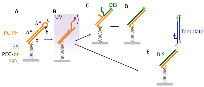
Figure 1: Bephore photolithography. A. A substrate with a surface of silicon dioxide (SiO2) is covered with a layer of biotinylated polyethylene glycol (PEG-bt), which is biocompatible and allows for the attachment of a photocleavable DNA hairpin via biotin-streptavidin interactions. Here, PC contains sequence domains abcb* and a photocleavable modification (purple star) and is hybridized to the strand PH with domain a*. B. Ultraviolet (UV) illumination cleaves PC, releasing a DNA fragment (cb*) into solution. C-D. The resulting single-stranded region on PC (b) aids as a toehold for the displacement of PH by a fluorescently labeled (green star) DIS strand. E. Also longer, double-stranded DNA ("Template") can be attached to the patterned surface. Such DNA is prepared by PCR with a primer carrying a DIS sequence at its 5' end, where primer and DIS are separated by a triethylene glycol spacer to keep DIS single-stranded during PCR (see also supplementary information, sections 2-4). Please click here to view a larger version of this figure.
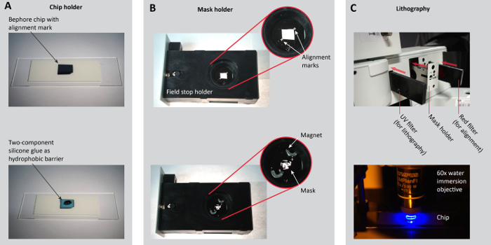
Figure 2: Sample preparation for photolithography. A. Place a Bephore chip with an alignment mark on a microscopy slide or another chip holder (e.g. the holder in Figure 3B). Apply two-component silicone glue as a hydrophobic barrier along the edges of the chip (steps 3.1.2-3). B. Place the mask onto a mask holder. Here, we removed the iris of the field stop and modified its holder so the mask can be held by small magnets. For precise (angular) alignment in multi-step lithography, ensure that alignment marks on the holder and the mask match (step 3.2.1). C. To navigate on the chip and to align the mask with the alignment marks on the chip, slide in the red filter. For the UV exposure, insert the UV filter (steps 3.2.2-5). Figure reproduced from the Supporting Information of previous work27. Please click here to view a larger version of this figure.
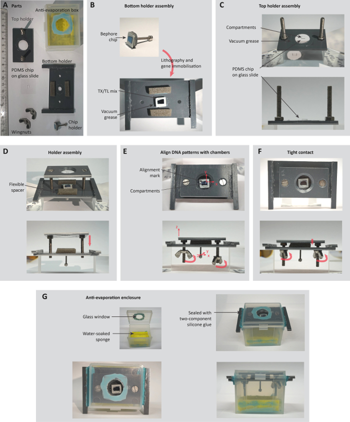
Figure 3: Assembly of a holder for the observation of compartmentalized gene expression. A. Parts of the holder (ruler unit: cm). B-C. Top and bottom part of the holder are assembled separately, with the bottom holder carrying a patterned Bephore chip (section 5.1) and the top holder carrying a PDMS chip with compartments (section 5.2). D-F. Chip and PDMS are carefully brought into tight contact, while simultaneously observing and aligning compartments and DNA brushes in a stereoscopic microscope (steps 5.3.1-6). G. Before transferring the holder to an inverted, temperature-controlled microscope, the whole system is encapsulated in an anti-evaporation box (steps 5.3.7-8). Figure reproduced from the Supporting Information of previous work27. Please click here to view a larger version of this figure.
Figure 4: Microfluidic setup and sample holder for the compartmentalized gene expression. A. Parts of the sample holder, the PDMS device, the temperature-controlled microscope stage and the Bephore glass slide (ruler unit: cm). B. A microscopy slide carrying the PDMS with compartments is glued to the PDMS holder and exposed to oxygen plasma together with the PDMS in a plasma cleaner. The PDMS is then inserted into the top holder (steps 6.2.2-5). C. The cell-free expression system tube is connected to a pressure controller and placed on ice. The tubing (red dashed line in the inset) for the cell-free expression system is cooled by rubber tubing (blue dashed line) through which ice water is pumped by a peristaltic pump (section 6.1). D. The tubing is connected to the inlet position on the PDMS device. Another piece of tubing is connected to the outlet (steps 6.2.6-7). E. The top holder is placed on the microscope stage and carefully lowered towards the Bephore slide. The PDMS holder can still be moved in the x-y-plane to align the compartments in the PDMS with the gene brush on the Bephore chip. The wingnuts are used to press the PDMS onto the Bephore chip and fix the top holder to the microscope stage (steps 6.4.1-3). F. Cell-free expression system is pumped through the micro-channels in the PDMS and gene expression from DNA brushes can be monitored in epifluorescence microscopy (step 6.4.4). Please click here to view a larger version of this figure.
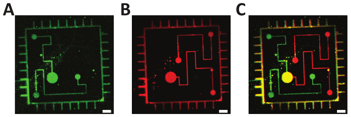
Figure 5: Two-step photolithography. A-B. Fluorescently labeled oligonucleotides (green: ATTO 532; red: Alexa Fluor 647) were consecutively immobilized on a Bephore glass slide via mask projection lithography with exposure times of 45 s. C. Overlay of subfigures A and B, demonstrating the precise alignment of the single exposures. Scale bars: 10 µm. Please click here to view a larger version of this figure.
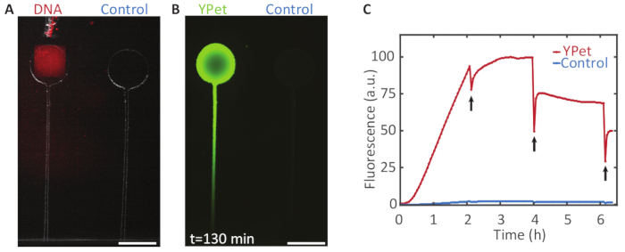
Figure 6: Compartmentalized gene expression. A. A DNA brush on a Bephore glass slide (UV exposure time: 2 min), coding for the fluorescent protein YPet was aligned with a compartment on a PDMS chip (see section 5 and Figure 3). B. Gene expression in the chamber with DNA yielded a strong fluorescence signal with a protein concentration gradient forming along a channel, which connected the chamber to the expression mix outside of the PDMS device. The control chamber without immobilized genes remained relatively dark. C. Fluorescence intensity profile over time for both chambers. Every two hours the fluorescent protein was partly bleached (black arrows) to check whether the expression was still active. After 4 h, the fluorescence did not recover to its previous intensity, indicating that expression had terminated. Scale bars: 300 µm. Please click here to view a larger version of this figure.
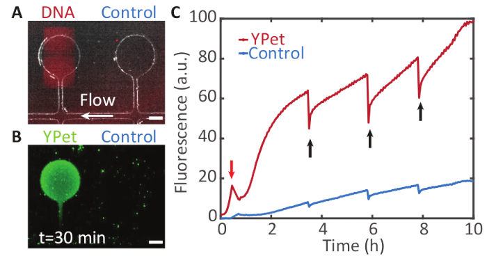
Figure 7: Sustained compartmentalized gene expression. A. A DNA brush on a Bephore glass slide (UV exposure time: 2 min), coding for YPet was aligned with a compartment on a PDMS chip. The compartments are connected to a supply channel (white arrow) through which cell-free expression system is pumped (see section 6 and Figure 4). B. The compartment containing the gene brush shows a fluorescence signal from YPet expression (in green) by the cell-free gene expression system. The neighboring compartment without a gene brush remains relatively dark. Fresh components of the cell-free expression system flow through the supply channel and diffuse into the compartments, while waste products are transported away. C. Fluorescence intensity profile over time for both chambers. The fluorescent proteins were partly bleached at different points in time (black arrows) to check whether expression was still active. Due to flow in the supply channel, gene expression was maintained for at least 10 h. (The peak in the red trace marked by the red arrow was caused by an air bubble that temporarily drained the solution from the compartments). Scale bars: 50 µm. Please click here to view a larger version of this figure.
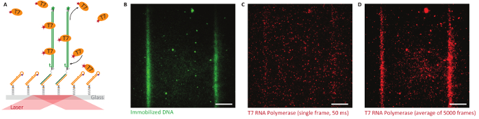
Figure 8: Single-molecule studies on Bephore glass slides in total internal reflection fluorescence microscopy (TIRFM). A. Objective-type TIRFM enables single-molecule imaging close to the glass-water interface. We immobilized fluorescently labeled genes (green, ATTO 532, UV exposure time: 2 min) with a T7 promoter along lithographically defined stripes and observed the behavior of T7 RNA polymerase (orange, labeled with Alexa Fluor 647) interacting with the surface. B. Fluorescence image showing two stripes of immobilized genes. C. T7 RNA polymerases attach specifically and non-specifically to the surface (single image, 50 ms exposure time). D. An average image obtained from all frames of a fluorescence video (5,000 frames like in subfigure C) exposes the specific interaction of the RNA polymerase with the DNA brush. Scale bars: 10 µm. Please click here to view a larger version of this figure.
Supplemental File 1. Please click here to download this file.
Supplemental File 2. Please click here to download this file.
Bephore lithography is a robust and versatile technique for the patterned immobilization of DNA or RNA. Yet, the procedure includes several steps, which – if changed – may be a source for failure or reduced performance of the system.
A crucial step in the fabrication of Bephore chips is the PEGylation of the substrate, which provides the biocompatibility of the surface. Here, the cleaning step with an RCA procedure is important, since it also activates the surface for the subsequent silanization. During the actual PEGylation, the substrate must not dry out. Furthermore, the Silane-PEG-Biotin must be stored properly to preserve its reactivity (section 1.2) and to avoid crosslinking. To assess the outcome of the PEGylation, substrates can be incubated with fluorescently labeled streptavidin and compared to non-PEGylated controls. Successfully PEGylated substrates should bind considerably more streptavidin than the controls.
Also, in later stages of the lithographic process, drying of the chip has adverse effects, resulting e.g. in the removal of already bound DNA or in a higher adsorption of DNA to unexposed regions on the substrate.
As mentioned above (section 3.2), the resolution of the lithographic process and the necessary exposure times depend on the experimental setup (objective, light source, etc.). Therefore, in a first step, a wide range of exposure times should be tested.
For gene expression experiments, the experimental setup should be customized to fit the available hardware (microscope, temperature control, etc.). We showed two such implementations, one for short experiments (4 h, section 5), where the system was encapsulated in a box to reduce the evaporation of the expression mix, and one for long observation (section 6), where a microfluidic device enabled a continuous supply of precursor molecules. In both cases, the alignment of DNA brushes on the substrate and compartments in the PDMS represented the trickiest step. We therefore recommend trying this step several times with a dummy substrate before using a patterned one (see also supplementary information, section 6). In the assembly of large systems of distinct gene brushes, long incubation times, precise angular alignment of chambers and brushes over long distances, and contamination by adsorption of DNA to non-patterned regions depending on the quality of passivation, may pose limitations to the size of practically feasible systems.
An alternative to this technique was demonstrated by Karzbrun et al.25, who created compartments in a chip by inductively coupled plasma reactive-ion etching (Bosch process), followed by plasma-enhanced vapor deposition (PECVD) of a silicon dioxide layer. After surface functionalization, patterning and placement of nanoliter DNA droplets by a pipetting robot, the compartments were closed with a PDMS-covered glass slide. This procedure has the advantage that the DNA can be directly immobilized inside the compartments without the danger of contaminating nearby chambers, but it requires additional fabrication steps and laboratory equipment.
The protocol presented here enables researchers working in cell-free synthetic biology to transfer their systems of study from solution-based setups to chip-based reaction containers. Utilizing DNA strand displacement as the central step during development of the resist enables labeling of exposed regions with unique DNA sequences, which provides a facile approach towards biocompatible multistep lithography. Combination with microfluidics allows the observation of gene expression processes over extended periods of time. Apart from the investigation of cell-free gene expression processes under open flow reactor conditions, the same methodology could be used to immobilize and spatially organize other biomolecules on a chip surface. This should prove useful for a wide variety of functional and biophysical studies, such as the fluorescence-based single-molecule experiments demonstrated here.
The authors have nothing to disclose.
We gratefully acknowledge financial support for this project by the Volkswagen Stiftung (grant no. 89 883) and the European Research Council (grant agreement no. 694410 – AEDNA). M.S.-S. acknowledges support by the DFG through GRK 2062.
Silicon wafer with 50 nm silicon dioxide (Bephore substrate) | Siegert Wafer | Thickness (µm): 525 ±25, Diameter (mm): 100 | |
Silicon wafer (for PDMS master mold) | Siegert Wafer | Thickness (µm): 525 ±25, Diameter (mm): 76.2 (3”) | |
Glass slides no. 4 | Menzel | 22 mm x 50 mm | |
Glass slides no. 1.5 | Assistent | 24 mm x 24 mm | |
Biotin-PEG-Silane | Laysan Bio | MW 5,000 | |
Anhydrous toluene | Sigma Aldrich (Merck) | 244511 | |
Streptavidin | Thermo-Fisher Scientific | S888 | |
DNA | Integrated DNA Technologies (IDT) | ||
Phusion High-Fidelity PCR Master Mix with HF Buffer | New England Biolabs | M0531S | PCR kit |
Wizard SV Gel and PCR Clean-Up System | Promega | A9281 | Spin-column PCR clean-up kit |
PURExpress | New England Biolabs | E6800S | Cell-free expression system |
PDMS | Dow Corning | Slygard 184 | |
FluoSpheres | Thermo-Fisher Scientific | F8771 | |
PTFE tubing (ID: 0.8mm, OD: 1.6 mm) | Bola | S 1810-10 | |
EpoCore 20 | micro resist technology GmbH | Photoresist | |
mr-Dev 600 | micro resist technology GmbH | Photoresist developer | |
Ti-Prime | MicroChemicals | Adhesion promoter | |
Two-component silicon glue | Picodent | Twinsil | |
UV-protection yellow foil | Lithoprotect (via MicroChemicals) | Y520E212 | |
Equipment | |||
Masks for photolithography | Zitzmann GmbH | 64.000 dpi, 180×240 mm | |
Upright microscope | Olympus | BX51 | Photolithography and fluorescence imaging |
60x water immersion objective | Olympus | LumPlanFl | Used with Olympus BX51, NA 0.9 |
20x water immersion objective | Olympus | LumPlanFl | Used with Olympus BX51, NA 0.5 |
Camera | Photometrics | Coolsnap HQ | Used with Olympus BX51 |
Ligtht source | EXFO | X-Cite 120Q | Used with Olympus BX51 |
Inverted microscope | Nikon | Ti2-E | Fluorescence imaging of gene expression |
4x objective | Nikon | CFI P-Apo 4x Lambda | Used with Nikon Ti2-E |
Camera | Andor | Neo5.5 | Used with Nikon Ti2-E |
Light source | Lumencor | SOLA SM II | Used with Nikon Ti2-E |
Cage incubator | Okolab | bold line | Used with Nikon Ti2-E |
Pressure Controller | Elveflow | OB1 MK3 | |
NanoPhotometer | Implen | DNA concentration measurement | |
Plasma cleaner | Diener | Femto | 200 W, operated at 0.8 mbar with the sample in a Faraday cage |